Table of Contents
Introduction
Analog I/O Wildcard Hardware
Connecting To Mosaic Controller
Selecting the Wildcard Address
Selecting the Reference Voltage
Analog I/O Wildcard Field Header
Software
Overview of the Software Device Driver Functions
Initializing the Analog I/O Software Drivers
Using the DAC Drivers
Using the A/D Drivers
Installing the Analog I/O Wildcard Driver Software
Using the Driver Code with C
Using the Driver Code with Forth
Glossary
Overview of Glossary Notation
Glossary Quick Reference
Glossary Entries
Hardware Schematics (pdf, 38.3KB)
|
Analog I/O Wildcard User Guide
Introduction
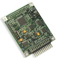 The Analog I/O Wildcard provides eight 12-bit digital to analog (DAC) outputs and eight 16-bit analog to digital (A/D) inputs. This tiny 2" by 2.5" module is a member of the Wildcard™ series that connects directly to Mosaic embedded controllers.
This document describes the capabilities of the Analog I/O Wildcard, tells how to configure the hardware, and presents an overview of the driver software. A glossary of the software functions and complete hardware schematics are also included. The Analog I/O Wildcard provides eight 12-bit digital to analog (DAC) outputs and eight 16-bit analog to digital (A/D) inputs. This tiny 2" by 2.5" module is a member of the Wildcard™ series that connects directly to Mosaic embedded controllers.
This document describes the capabilities of the Analog I/O Wildcard, tells how to configure the hardware, and presents an overview of the driver software. A glossary of the software functions and complete hardware schematics are also included.
The Analog I/O Wildcard comprises a Wildcard bus header, field header, digital logic circuitry, an octal 12-bit digital to analog converter (DAC), an octal 16-bit analog to digital converter (A/D), and a 4.096 volt reference. The 4.096 reference voltage varies less than 100 microvolts per degree Celsius change in temperature. Jumpers enable module address selection and reference voltage selection among 5V, 4.096V, the DAC reference voltages (1.024 or 2.048 V), or an external reference voltage. The Wildcard bus header interfaces to the host processor (Mosaic embedded controller), and the field header brings out the analog I/O signals for the reference, DAC, and A/D. Specifications are summarized in Table 1-1.
Table 1-1 Analog I/O Wildcard Specifications
| Analog Inputs |
| Channels: |
8 unipolar single-ended, or 4 unipolar differential inputs |
| Resolution: |
16-bits ( 0 - 65,535 counts) |
| Input Filtering: |
Land patterns are provided for optional input RC filters |
| Input Voltage Range: |
+IN: -0.2 V to 5.2 V
-IN: -0.2 V to 1.25 V |
| FS Differential Range: |
Jumper selectable full scale (FS) reference: 1.024 V, 2.048 V, 4.096 V, 5.0 V, or external. |
| Excitation: |
Jumper selectable excitation output voltage of: 1.024 V, 2.048 V, 4.096 V, or 5.0 V. |
| Non-Linearity: |
Integral: ± 8 LSB max, ± 3 LSB typ;
Differential: ± 1 LSB typ |
| Noise and Accuracy: |
20 uV rms effective input noise; 14.4 bits effective resolution |
| Sample Rate: |
Up to 17k samples per second |
| Analog Outputs |
| Channels: |
8 unipolar outputs |
| Resolution: |
12-bits ( 0 - 4095 counts) |
| Output Filtering: |
Land patterns are provided for optional output RC filters |
| Output Voltage Range: |
Jumper selectable: 2.048 V, 4.096 V, or 2x external reference; 4.6 V max. |
| Settling Time: |
1 microsec typically, slew rate is typically 10V/microsec |
| Load Impedance: |
Capable of driving 2 kOhm minimum resistance, 100 pF maximum capacitance, see data sheet for load regulation |
| Non-Linearity: |
Integral: ± 2 LSB max;
Differential: ± 0.5 LSB typ |
| Update Rate: |
Up to 15k samples per second |
| Next>>
|

