

 |
 |
 |
Table of ContentsConnecting To Mosaic Controller RS422/485 Configuration Jumpers Protocol Configuration and Direction Control Registers Overview of the Software Device Driver Functions Installing the UART Module Driver Software Using the Driver Code with Forth UART Direction Control in a Multitasking System C Demonstration Program (in pdf) |
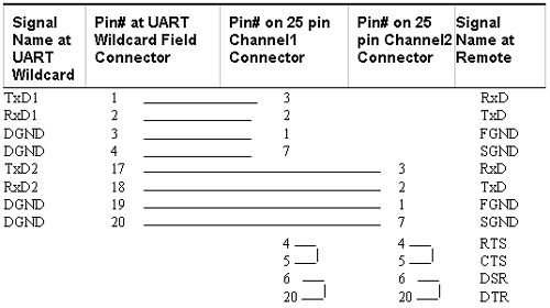
UART Wildcard User GuideCable ConnectionsThis section presents some suggested cable connections for common protocols. Each application will typically require a custom cable assembly to meet the needs of that project.Table 1-5 Cable for Dual RS232 25-pin D Connectors  Table 1-5 illustrates the connections required to implement two RS232 ports, each using a standard 25-pin D-type connector. Note that TxD at the local UART Wildcard connects to RxD at the remote, and the local RxD connects to TxD at the remote. Also note that the RS232 handshaking signals RTS and CTS are connected to each other with a shorting wire at the D connector. Similarly, the RS232 handshaking signals DSR and DTR are connected to each other at the D connector. This standard scheme makes the remote computer think that it is always OK to send and receive data. A cable that supports a modem on channel 1 is shown in Table 1-6. Note that the handshaking signals are brought out to the 25 pin D-connector. The CTS1 (clear to send) input to the UART Wildcard connects to the RTS (ready to send) output from the remote. The DSR1 (data set ready) input to the UART Wildcard connects to the DTR (data terminal ready) output from the remote. The DTR1 and RTS1 outputs from the UART Wildcard connect to the DSR and CTS inputs to the remote, respectively. The DCD (data carrier detect) modem output connects to the RxD2/DCD1 input on the UART Wildcard. Because this pin is shared with RxD2, Channel2 cannot be configured for RS232 when a modem is in use. In this case, the user is free to implement RS422 or RS485 on Channel 2. Table 1-6 Cable for an RS232 Modem via a 25-pin D Connector  |
Home|Site Map|Products|Manuals|Resources|Order|About Us
Copyright (c) 2006 Mosaic Industries, Inc.
Your source for single board computers, embedded controllers, and operator interfaces for instruments and automation