Serial LCD Character Displays
Mosaic offers two serial LCD displays with your choice of 4 lines by 20 characters, or 2 lines by 16 characters. A simple 3-wire interface (power, ground, and serial data) connects the display to any Mosaic controller (PDQ Board, QCard, QScreen, QVGA, or Handheld). Starter cables are available from Mosaic when you purchase your display.
The following provides a brief description of how to get started using the serial display. In addition to this documentation page, you can download these *.pdf user guides:
These detailed pdf-format user guides provide complete mechanical, electronic, and software specifications for the displays. Consult them for mechanical drawings.
Specifications
Two displays are available, a 2 line by 16 character display and a 4 line by 20 character display. Both use STN, positive, transflective LCD technology with black characters on a yellow/green-backlit gray background.
| Part number | Logical size | Overall size | Visible area | Power requirement |
|---|---|---|---|---|
| LCDS-216 | 2 lines by 16 characters | 36 x 80 x 13.5 mm (1.42 x 3.15 x 0.53 in.) | 16.4 x 64.5 mm (0.64 x 2.5 in.) | 5V at 12 – 96 mA (depending on backlight setting) |
| LCDS-420 | 4 lines by 20 characters | 60 x 98 x 13.5 mm (2.36 x 3.86 x 0.53 in.) | 25.2 x 76 mm (1.0 x 2.5 in.) | 5V at 12 – 96 mA (depending on backlight setting) |
On either display you may set the backlight intensity from 1 to 8, corresponding to a total current draw of 12 mA to 96 mA.
Connecting the displays
The serial liquid crystal display (LCD) module connects via a custom cable to the Mosaic microcontroller board. The connecting cable can be purchased from Mosaic Industries.
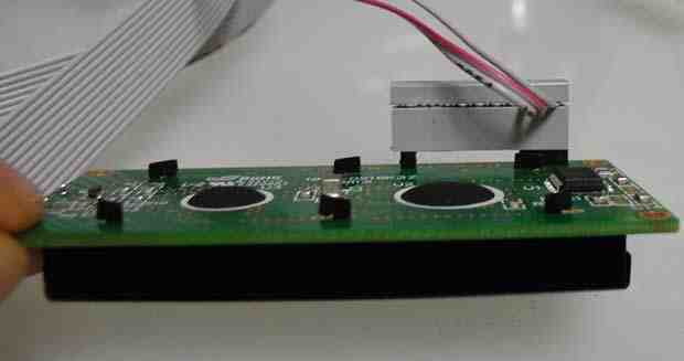
Three wires provide the interface to the LCD: the logic-level serial receive signal Rx, ground, and +5V power. On the LCD module, the three relevant wires are brought to positions 1 through 3 of a single in-line 10-position header. The extra 7 pins are not wired, and are designed to prevent backward installation of the header on the display; pin 10 is installed but not connected to provide additional mechanical stability. Rx is the signal nearest to the corner, ground is the next pin, and +5V is the 3rd pin from the corner.
On the Mosaic controller board, ground is pin 1 and +5V is pin 2 on the digital field header (header H2 on the QCard or H8 on the PDQ Board). Using a QCard or QScreen controller, the logic-level serial signal originates at pin PA4 (serial2 transmit on the QCard), which is pin 12 on the QCard field header (H2). Using a PDQ Board or PDQScreen, the logic-level serial signal originates at pin XCV2+ (the positive RS485 serial signal) which is pin 4 on the Comm header, H2.
For the QCard, the cable is wired to connect the following pins (one connection per row):
| 10-pin Display Connector | QCard (H2) | Signal name |
|---|---|---|
| 1 → | ← 12 | Display Rx, QCard TxD2 |
| 2 → | ← 1 | GND |
| 3 → | ← 2 | +5V |
For the PDQ Board, the cable is wired to connect the following pins (one connection per row):
| PDQ Board (H8) | 10-pin Display Connector | PDQ Board (H2) | Signal name |
|---|---|---|---|
| 1 → | ← 2 | GND | |
| 2 → | ← 3 | +5V | |
| 1 → | ← 4 | Display Rx, PDQ Board XCV2 |
![]() If you are using a PDQ Board or PDQScreen, the Serial2 RS485 must be enabled by installing a jumper on the Mosaic controller board. On the PDQ Board, install the 7th jumper below the reset button, labeled "485En" in the "2" section of the jumper pack. On the PDQScreen, install the 10th jumper to the right of the reset button, labeled "485-2."
If you are using a PDQ Board or PDQScreen, the Serial2 RS485 must be enabled by installing a jumper on the Mosaic controller board. On the PDQ Board, install the 7th jumper below the reset button, labeled "485En" in the "2" section of the jumper pack. On the PDQScreen, install the 10th jumper to the right of the reset button, labeled "485-2."
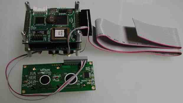
Here is a picture of a QCard field header driving the interface cable to a 2x16 display:

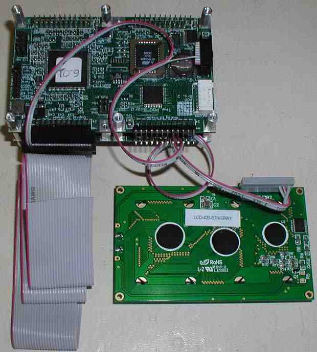
Here is a picture of a PDQ Board digital field header and comm header driving the interface cable to a 4x20 display:

Here is a close-up of the cable connection to the back of the 2x16 display:

Writing characters to the display
The LCD module is configured by Mosaic to run at 1200 baud, and this value is stored in nonvolatile memory in the LCD module. After a power-up, the display comes on with the cursor homed to the upper left corner, and the backlight is on. After initializing the controller serial channel as described below, the Emit2 function can be used to write characters to the display as shown in the code examples below. Another way to write to the display is to set up a task and invoke UseSerial2 in the task activation routine. Then standard print routines like printf can be used to write to the LCD module from within the task.
Writing characters from QCard or QScreen controller
After initializing the serial2 port, setting the serial2 baud rate, and enabling interrupts using StartTimeslicer or ENABLE_INTERRUPTS, characters can be written to the display by invoking Emit2 to send the ASCII values to the LCD module. For example, the following C instructions print “Hi!” to the display:
InitSerial2();                       // initialize serial2 port
Baud2(1200);                         // set 1200 baud on serial2
StartTimeslicer();                   // enable interrupts
Emit2('H'); Emit2('i'); Emit2('!');  // write Hi! to the display
Writing characters from a PDQ Board or PDQScreen controller
The PDQ controllers use the serial2 RS485 XCV2+ output to write to the display. After initializing the serial2 RS485 channel, characters can be written to the display by invoking Emit2 to send the ASCII values to the LCD module. For example, the following C instructions print "Hi!" to the display:
RS485Init();                         // initialize RS485
RS485Transmit(2);                    // serial2 RS485 is in transmit mode
Baud( 12, 2 );                       // set 1200 baud on serial2
Emit2('H'); Emit2('i'); Emit2('!');  // write Hi! to the display
Command sequences
The display module can be turned on or off, the display can be cleared, the backlight intensity can be set, and the contrast can be controlled via software commands. These command sequences are described in detail in the user guides:
Backlight intensity and current drain
The backlight defaults to an intensity level of 5 on a scale of 1 to 8 (note that a backlight intensity of zero is not allowed and can lead to unpredictable display operation). While a higher backlight intensity may enhance display visibility, the transflective display is visible in a variety of ambient light conditions even without the backlight. To minimize power drain, the backlight could be set to its minimal level of 1 using these commands:
Emit2(0xFE); Emit2(0x53); Emit2(1); // set backlight intensity to 1
The typical current consumption of either the 2x16 or 4x20 display can be calculated as:
   Current = (12mA)*(Backlight_Intensity)
     where Backlight_Intensity is an integer between 1 and 8.
Thus the minimum typical current drain of the display is 12mA if the Backlight_Intensity is set to 1. At the default Backlight_Intensity of 5, the display draws about 60 milliamps.
Adjusting the display contrast
The display contrast can be changed under software control to any level between 1 and 50, with a default value of 40. This allows an application program to provide a way for the user to change the contrast, which is sometimes advisable in instruments that experience wide swings in ambient temperature. For example, to change the display contrast to 35, the application program would execute these three commands:
Emit2(0xFE); Emit2(0x52); Emit2(35); // set contrast to 35
Clearing the screen
The screen can be cleared and the cursor homed to the upper left corner of the display using this command sequence:
Emit2(0xFE); Emit2(0x51); // clear the screen and home the cursor
As described in the user guides, a variety of other software commands are available for controlling the cursor style and location, and writing special characters to the display.
Initializing the display baud rate
The serial displays ship from Mosaic with the baud rate set to 1200 baud. This baud rate is retained in non-volatile memory on the display. If the display baud rate is not at the default and is configured to any baud rate up to 9600 baud, a pre-coded program is available from Mosaic to set the display rate to 1200 baud. Here is the source code:
Display Baud Rate Re-Initialization Program
  1: // Initialize baud rate and backlight on Serial LCD  2011-06-22
  2: // This C code is meant to be compiled, then downloaded after a COLD restart
  3: //
  4: //  Serial LCD is interfaced using 3 wires:
  5: // +5V      H2 Header on QCard:   Pin 2
  6: // Ground   H2 Header on QCard:   Pin 1
  7: // Serial   H2 Header on QCard:   Pin 12 (PA4)
  8:
  9:
 10: // this include statement should appear at the top of each source code file.
 11: #include <mosaic\allqed.h>
 12:
 13: #define min(a,b) ((a)>(b)?(b):(a))
 14: #define max(a,b) ((a)<(b)?(b):(a))
 15:
 16:
 17: _Q Backlight( int level )
 18: {   // set backlight to the specified level
 19:     // between 1(low intensity) and 8 (high intensity)
 20:     level = min( level, 8 );
 21:     level = max( level, 1 );  // clamp to allowed range: 1 to 8
 22:     Emit2( 0xFE );
 23:     Emit2( 0x53 );
 24:     Emit2( level );  // write backlight-setting command to display
 25: }
 26:
 27: void Set_Baud_1200( void )
 28: {  // carefully set the baud rate of the display to 1200 baud, the Mosaic default
 29:     MicrosecDelay(-1);
 30:     Emit2(0xfe);
 31:     MicrosecDelay(-1);
 32:     Emit2(0x61);
 33:     MicrosecDelay(-1);
 34:    Emit2(2);
 35:    MicrosecDelay(-1);
 36: }
 37:
 38: void Clear_Screen( void )
 39: {
 40:     MicrosecDelay(-1);
 41:     Emit2(0xfe);
 42:     Emit2(0x51);  // clear the screen and home the cursor to the upper left
 43: }
 44:
 45: void Default_Backlight( void )
 46: {
 47:     MicrosecDelay(-1);
 48:     Backlight(5);  // set the backlight to default level of 5
 49: }
 50:
 51: #ifdef __GNUC__    // for V6.xx kernels (PDQ Board, PDQScreen)...
 52:
 53: void Display_Serial_Init( void )
 54: {
 55:     RS485Init();                         // initialize RS485
 56:     RS485Transmit(2);                    // serial2 RS485 is in transmit mode
 57: }
 58:
 59: void Display_Serial_Baud( int baudrate )
 60: {
 61:     Baud( (baudrate/100), 2 );  // set baud on serial2
 62: }
 63:
 64: #else  // for V4.4x kernels (QCard, QScreen, Handheld)...
 65:
 66: void Display_Serial_Init( void )
 67: {
 68:     InitSerial2();                       // initialize serial2 port
 69:     Baud2(1200);                         // set 1200 baud on serial2
 70:     StartTimeslicer();                   // enable interrupts
 71: }
 72:
 73: void Display_Serial_Baud( int baudrate )
 74: {
 75:     Baud2(baudrate);       // set baud on serial2
 76: }
 77:
 78:
 79: #endif
 80:
 81: _Q Baud_Recover( void )
 82: // baud codes: 1: 300  2: 1200  3: 2400  4: 9600  5: 14400 6: 19200 7: 57600  8: 115200
 83: // This routine can recover from incorrect baud rates up to 9600 baud, not beyond.
 84: // Inits serial2, then tries at each baud rate to reset display baud to 1200.
 85: // Then inits backlight, puts "ok!" on display.
 86: // Note: some transient characters may appear on the display while this
 87: // routine re-sets the baud rate; they will disappear when Clear_Screen is called.
 88: // These characters will not affect instrumentation
 89: {
 90:    Display_Serial_Init();
 91:
 92:     Display_Serial_Baud(9600);
 93:     Set_Baud_1200();
 94:
 95:     Display_Serial_Baud(2400);
 96:     Set_Baud_1200();
 97:
 98:
 99:    Display_Serial_Baud(300);
100:     Set_Baud_1200();
101:
102:     Display_Serial_Baud(1200);
103:     Set_Baud_1200();
104:
105:
106:     Clear_Screen();       // clear the screen and home the cursor
107:     Default_Backlight();  // set backlight intensity to 5
108:    Emit2('o');
109:    Emit2('k');
110:    Emit2('!');  // put ok! on screen when we're done
111: }
112:
113:
114: void main( void )
115: {
116:     Baud_Recover();
117: }
Physical dimensions
Please consult the pdf versions of the users guides for detailed physical dimensions of the displays:
Technical support
Please Contact Us if you have any questions about this product.
