Cell Constant of Parallel Wire Electrodes
Solving Gauss's Law electric field equations for a paraxial two-electrode conductivity cell
This page provides the solutions to three related problems that involve electric fields of similar geometry:
- Finding the cell constant of a two-electrode conductivity cell using parallel wire, cylindrical or tubular electrodes;
- Finding the capacitance between two long paraxial cylinders (or, the capacitance of twin-lead, the capacitance between parallel wire electrodes, the capacitance of transmission lines, the capacitance of cables, or the capacitance of power lines);
- Finding the resistance or conductance between two non-intersecting circular contacts on an infinite sheet of conducting material of uniform resistivity.
Using Gauss's law for electric fields of the appropriate geometry we find a general solution for all three problems.
Paraxial two-electrode conductivity cells
The most commonly used conductivity probes for measuring the conductance of electrolytic solutions use a two electrode cell. Often the electrodes are metal plates or concentric tubes. Glass cells use platinum electrodes and epoxy cells use more easily cleaned graphite plates.

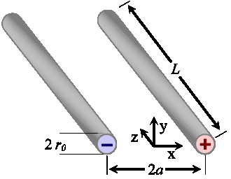
A particularly convenient and inexpensive design for two-electrode conductivity cells uses two simple wire or tubular electrodes, often composed of stainless steel. Figure 1 shows the geometry; two parallel cylindrical metal electrodes are immersed in a medium of uniform conductivity, σ, such as an electrolytic solution.
Each of the parallel wires is of radius r0, lies parallel to the z-axis, and is separated along the x-axis by a distance 2a.
Calculating the cell constant for parallel wire electrodes
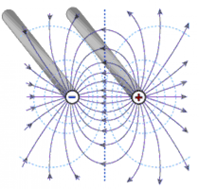
To find the cell constant we'll consider the geometry of the electric field around the electrodes, as shown in the following figure. The field is produced by a uniformly distributed charge per unit length, λ, on each electrode. For now we'll assume that each electrode's length, L, is much greater than their separation, 2a, so that we can ignore the effect of fringing fields around the electrode ends. Consequently, there is no component of electric field in the z-direction.
Figure 2 shows the electric field in the x-y plane at z=0. The electric field lines begin and end on the electrodes. The figure also shows isopotential lines circling the electrodes. The current between the electrodes follows the field lines, being proportional at each point to the media's conductivity and the electric field magnitude at that point.

To find the cell constant, we'll take the following steps:
- Assuming a charge per unit length of λ, and considering the geometry of the electrodes, we'll find the electric field in the space between the electrodes and the voltage between the electrodes. From the voltage and charge we can then compute the capacitance.
- Recognizing that all the current between the electrodes passes through the y-z plane at x=0, and noting that the electric field at x=0 is strictly directed along the x-axis, we'll compute the total current between the electrodes.
The conductance,
G = I/V,
is the ratio of current to voltage. We'll find the cell constant, K, as the proportionality constant of conductance to conductivity, as,
K = σ/G.
Inter-electrode voltage
When a voltage is applied to the paraxial electrodes they charge, with a charge per unit length of λ, creating an electric field between the electrodes. Gauss's law relates the electric flux emanating from a closed surface to the contained charge, Q and the dielectric constant of the media, k, as,
where εo is the permittivity of free space.
We solve this integral for the radial electric field intensity for each of the parallel cylinders separately (we'll later use superposition to add the two components), obtaining,
where r>r0 is the distance from the axis of the wire electrode, and r0 is the electrode radius.
The total electric field at each point is simply the sum of the radial electric fields from each of the parallel wires. That combined field is purely in the x direction along the x axis and at x=0 where the field crosses the y-z plane. We find the field along the x-axis between the two electrodes by summing the components from each electrode as,
Similarly, we find the field normal to the y-axis (that is, normal to the y-z plane at x = 0. Again, it is directed purely in the x-direction,
As the electric field is conservative, the voltage between the electrodes is the line integral of the electric field along any path from one electrode to the other. We choose the simplest path, directly along the x-axis to integrate as,
Eqn. 5 shows the inter-electrode voltage to be proportional to the electrodes' charge.
Capacitance between paraxial cylindrical wire electrodes
The capacitance of parallel wires
We can also compute the inter-electrode capacitance as the ratio of charge to voltage as,
The capacitance depends on the media's dielectric constant, k. Note that this capacitance ignores the interfacial capacitance of any electric dipole double layers at the electrode surface. Such an interfacial capacitance depends on the microscopic structure of the electrode surface. Instead, this capacitance is the capacitance that depends only on the gross geometry of the parallel cylinders and the bulk dielectric constant of the media, for media without freely moving ions.
In short, Equation 6 provides the capacitance between two parallel wires in a medium of uniform dielectric constant. With minor modifications this formula can be used for:
- the capacitance of twin-lead,
- the capacitance between parallel wire electrodes,
- the capacitance of transmission lines,
- the capacitance of wire cables, or ,
- the capacitance of power lines, or electrical transmission lines.
Inter-electrode current
Now that we know the voltage across the media, to find the conductance we still need to find the current through the media. We do that by integrating the current flux through any surface that fully encloses one electrode or fully separates the two electrodes. We'll do it across the y-z plane, where the electric field vector is parallel to the x-axis, as,
Conductance and cell constant
We find the conductance of the media between and around the electrodes as the ratio of the current to voltage,
The cell constant is the ratio of conductivity to conductance. Combining Equations 5, 7, and 8 we find,
As we might expect, the cell constant is inversely proportional to the electrode length, L. Its logarithmic dependence on electrode radius and separation is weak for a separation of more than a few radii. Consequently, the cell constant is fairly forgiving of manufacturing inaccuracies in electrode placement.
More explicitly, relative change in cell constant with respect to a relative change in a/ro is given by the derivative,
The value of this derivative is 0.5 at a/ro ≈ 5 decreasing to 0.33 at a/ro ≈ 12 and 0.25 at a/ro ≈ 30. So, at a/ro ≈ 5 a 1% change in a/ro produces a 0.5% change in cell constant, with diminishingly less sensitivity at greater a/ro.
The effect of fringing fields
In the derivation above we have ignored the effects of fringing fields around the ends of the cylindrical electrodes, assuming that the length of the electrodes, L, is sufficiently greater than the electrode separation, 2a. However, most practical electrode designs will have significant fringe fields. Fringe fields have the following effects:
- The inter-electrode capacitance is increased.
- The inter-electrode current increases as current flows through the increased volume of media accessed by the ends of the electrodes. That increases the conductance, and decreases the cell constant.
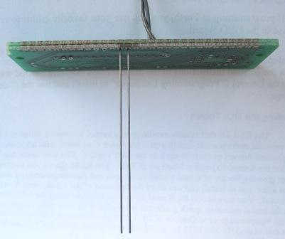
Fringing field effects are difficult to calculate analytically, but they can easily be measured. In an effort to quantify the conductance contribution of the fringing field we built a prototype conductivity sensor, shown in Figure 3. The sensor comprises two parallel graphite electrodes, each with a length of 60 mm and diameter of 0.53 mm (0.021"), and separated center-to-center by 2.59 mm (0.102"). The electrodes used are Pentel™ Super Hi Polymer HB 0.5mm pencil "leads". The composition of these leads is a synthetic resin, graphite and carbon. The material was chosen as one with a likely large BET surface area in comparison to that of metal wire electrodes. The resistance of the electrodes is 0.5 Ω/cm indicating a conductivity of the graphite composition of 409 S/cm.
The electrodes were soldered into plated-through holes on a piece of PCB. For stability, two PCB layers of 0.065" thickness each were used. Although we didn't expect the 60/40 Sn/Pb solder to adhere to the graphite rod, it did fill the plated-through hole binding the rod tightly and with good electrical conductance. The following photo shows the assembly.

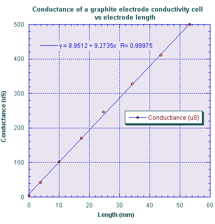
We slowly immersed the electrode assembly into a sodium chloride solution with a conductivity of 66 ±1 μS/cm. The solution was prepared by repeated dilution of a much greater NaCl concentration solution. The solution was contained in a deep cylindrical vessel 36 mm in diameter (14x the electrode separation). The measured conductance as a function of the immersion depth (the length of the electrodes, L) is shown in the following graph.

Note that the conductance increases linearly with depth as it should, but that there is an additional conductance, the small intercept on the graph, owing to the effect of the fringing field at the electrode ends. It has two components: as small distortion of the electric field at the top of the electrodes where they enter the solution, and a likely much larger fringing field at the bottom of the electrodes where the electric field is free to extend below the electrodes.
We identify the conductance contributed by the fringing fields as the intercept in the graph of Figure 4. Its magnitude is about that contributed by 1 mm of length – in effect the end-effect makes the electrodes appear about 1 mm longer (which is about twice the diameter of the electrodes) than they would be if there were no fringing field present. So the error due to fringing is not large, but nevertheless must be accounted for if precise measurements are to be made.
The dependence of conductance on length should agree with the cell constant we found in the equations above. Calculating the expected conductance change with electrode length from Eqn. 9 above we expect dG/dL = 9.5 μS/mm, not too far from the measured value of about 9.27. The small error is likely due to errors in our measurement of the electrode diameter and the influence of the finite diameter of our test vessel.
This test suggests a method for measuring the conductivity of a liquid without the influence of the fringing field around the electrode ends. If a measurement is taken at two or more immersion depths the slope of the above graph is easily measured. That slope depends only on the solution conductivity and the ideal cell constant, without any influence of electrode end effects.
Measuring surface resistivity using circular electrodes
The resulting cell constant can be applied to the problem of finding the resistance between two non-overlapping circular contacts on an infinite sheet of conductive material with uniform surface resistivity.
We consider the case of the above geometry as the length of the cylindrical electrodes goes to zero and the sampled media is diminished to a thin sheet of material. In that case, we identify the surface resistivity, ρS as,
where the surface resistivity is measured in ohms, or, to distinguish it from resistance, as ohms per square (Ω/□ or Ω/sq).
The surface resistance, R, is given by the ratio of voltage to current. Combining Equations 5 and 7 above,
The "cell constant" (or "sheet constant of resistivity"), K', which you multiply by measured resistance to find the surface resistivity, is then,


