A/D Protection Circuits
Protect an analog-to-digital converter from excessive or negative input voltages
You can protect an ATD converter from excessive or negative input voltages by using a Schottky diode and current limiting resistor. For example, you might be using an A/D to measure the output of a sensor that is specified to produce a 0-5V output signal. However, you find that under some fault conditions the sensor actually produces a negative output, or an output greater than 5V. In that case, a circuit protection device is needed to prevent damage.
Many A/D converter chips are sensitive to these out-of-specification input voltages and may be damaged. In general, A/D chips have internal parasitic substrate diodes that become forward biased if an input pin voltage exceeds the supply voltage to the chip by more than a diode drop, or has an excursion below ground by that much. If the current into the pin is sufficiently limited that usually doesn't cause damage. But to maintain the A/D's accuracy you usually can not use too much series resistance, so the input current may not be limited. Too much current flowing into the input pin of an A/D under these fault conditions can cause internal heating, destruction, or latch-up of the part. If latch-up occurs, it is generally remedied only by powering off the chip.
Using Schottky diodes and current limiting resistors to protect digital and analog inputs
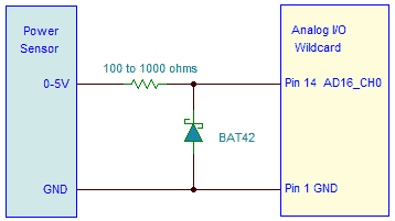
The classic way to protect the downstream A/D from the negative voltage is with a resistor-diode protection circuit like the following:

The circuit shows a current-limiting series resistor and a Schottky diode to ground used to protect A/D inputs from a "Power sensor". The "Power sensor" is meant to typify any device which may output an out-of-range signal that must be measured. This circuit is shown protecting an A/D converter input on Mosaic's Analog I/O Wildcard.
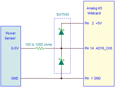
You can protect against positive excursions of the input voltage beyond the supply rail also, by including another diode, as shown in this figure:

Choosing values for circuit protection devices
Choose the resistor and diode values as follows:
- The resistor should be large enough to limit the current into the diode when a negative input voltage is applied, but small enough so that its voltage drop under normal conditions doesn't adversely affect the A/D converter readings. The 16-bit resolution A/D used on the Analog I/O Wildcard has a typical input leakage current of ±1 μA. That and the leakage current of the diode flowing through the resistor creates a small offset in the A/D readings. For a resistance of 100 Ω or less the error is negligible; for a resistance of 1 KΩ the error may be as much as 0.05% of full scale – still negligible for most applications. See the discussion of source resistance limitations for A/Ds for more info.
You may mount the resistor/diode externally to the A/D board, or in some cases there may be room reserved on the A/D board itself. In the case of Mosaic's Analog I/O Wildcard, there are land patterns reserved for resistor-capacitor filters or resistor-diode protection.
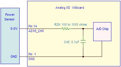
The following figure shows an RC filter mounted directly on the A/D board. Each input channel has reserved space for a series resistor, and a component (either capacitor or diode) to ground:

Only one channel is shown, AD16_CH0. The component locations use designators R29 and C40. As manufactured, R29 is populated with a zero ohm resistor (that is, a short), and nothing is placed on the capacitor pads at C40. You may replace the zero ohm resistor with any value of your choosing, and mount a capacitor for filtering.
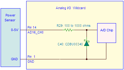
You may also use these locations to mount circuit protection components, as shown here:

The series resistor should be in the range of 100 Ω to 1 KΩ. The error caused by a resistance of 100 Ω will be smaller than you can measure, while a 1 KΩ resistor will cause an error of less than 0.05% (assuming a 2 μA leakage current into the A/D and diodes).
The figure shows the resistor replaced with a 100 Ω or 1 KΩ surface mount resistor (in a 0603 package), and a schottky diode (also in a 0603 package) placed at location C40. A good diode to use would be CDBU00340 available from Digikey.
The Analog I/O Wildcard's circuit schematic, found here, shows the designators used for the filtering/protection pads for each of the input channels.
Resources:
