Measuring Thermistors
You can generally measure the resistance of thermistors with 12-bit, 16-bit or 24-bit resolution A/Ds. If you don’t need much accuracy you could even use an 8-bit A/D. But, if you want the greatest accuracy possible, the required measurement resolution should be enough so that it doesn't degrade the thermistor’s innate accuracy; what you want is for the overall accuracy of the measurement to be limited by the thermistor itself rather than the measurement technique. A ±0.1°C change corresponds to a resistance change of about 0.5%. So the resistance must be measured to within ±0.5% over the range – that's not a problem using either the Analog I/O Wildcard or the 24/7 Data Acquisition Wildcard.
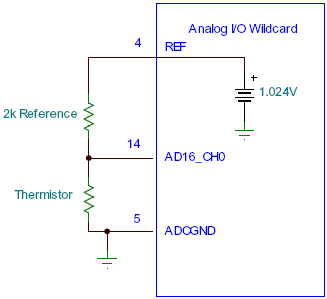
The resistance is measured by placing the thermistor in a voltage divider circuit with a reference resistor, as shown in the following figure. To obtain best use of the A/D input voltage range the value of the reference resistor should be approximately the same as the thermistor value around the temperatures of interest. For example, for the US Sensor PS222J2 thermistor with a resistance of 2252 ohms at 25°C, produces thermistor resistances of 12.5 KΩ - 560 Ω in the temperature range of -10°C to +60°C (with a geometric mean of about 2600 Ω). A reference resistance near the geometric mean of 2.6 KΩ should be chosen. 2.2 KΩ and 2.7 KΩ are commonly available, though in some cases a higher resistance value needs to be chosen to limit current drawn from the reference voltage and power dissipation in the thermistor. The reference resistor used should be of high accuracy, 0.25% or better. Precision resistors of ±0.1% are readily available from sources such as Digikey.
The above figure shows the pin numbers used for connections to the Analog I/O Wildcard’s field header, assuming that you are using input channel 0. You may use any of the other analog inputs instead. To minimize temperature rise due to power dissipation in the thermistor, the Wildcard should be configured to provide an excitation reference voltage of 1.024 volts on the field header (jumpers J3 & J6 installed, J4 & J5 not installed, configured in software intialization for 1.024V reference).
Keep in mind that the connectors you use should not introduce contact resistances that would be more than 0.5% of the lowest value of resistance to be measured (not a problem for most connectors).
The resistive divider circuit provides the thermistor voltage, vth, to the A/D. The voltage depends on the resistive divider as,
where vref is the A/D reference voltage used to drive the resistor divider.
The Analog I/O Wildcard provides a measure of that voltage input as a number of counts, C, with the maximum number of counts corresponding roughly to the reference voltage. More precisely, an n-bit A/D returns a number of counts, C, as,
where the A/D rounds C to the nearest integer from 0 to 2n-1. The voltage is most accurately computed from the number of counts as,
Combining the above equations, the thermistor resistance can be computed from the A/D counts, C, as,
The thermistor resistance may now be converted to temperature using the Temperature-Resistance Equation.
See also → Measuring Thermistors


