

 |
 |
 |
Table of ContentsConnecting to the 24/7 Data Acquisition Module Converter Noise and Effective Resolution Other Sources of Noise and Offset Error Tips For Measuring Small Voltages Addressing the 24/7 WildCard Using Module Select Jumpers Initializing the 24/7 Data Acquisition Wildcard Specifying the Reference Voltage Calibration Options Single- and Multi-Channel Sampling Continuous Sampling from a Single Channel |
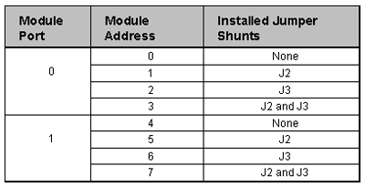
24/7 Data Acquisition Wildcard Users GuideOther Sources of Noise and Offset ErrorThermocouple junctions formed by the connection of dissimilar metals anywhere in the source circuit cause small errors. Junction potentials and Seebeck voltages are each a few microvolts per degree centigrade. So, unless extreme care is taken to cancel or compensate their effects they can be significant. The A/D's system calibration feature can compensate these at a single temperature, but it's hard to compensate them over a wide temperature range. Tips For Measuring Small VoltagesWhen measuring small voltages with the DA24/7 Wildcard you should use twisted pairs of wires between the signals and the analog inputs of the Wildcard. Try to keep the wires as short as possible to reduce the noise that will be coupled into the A/D converter. You should also be aware of the thermocouple effect that can add microvolts of temperature dependent offset to a signal. It is difficult to completely prevent thermocouple effects, but a few precautions can minimize them. Whenever possible use twisted pair wires of the same type extending from the voltage to be measured and terminated at the field I/O connector. To accurately measure small voltages, use the System Offset Calibration. The different calibration options will be covered in detail in the Software Section. The System Offset Calibration requires you to short the field inputs of the module together (at the sensor) during the calibration sequence to remove any offsets between the field inputs of the module and the inputs of the A/D Converter. Offsets can be as great as 100 microvolts if a System Offset Calibration is not preformed. Addressing the 24/7 WildCard Using Module Select JumpersTable 2: Jumper Settings and Associated Addresses The Module Select Jumpers, labeled J2 and J3, select a 2-bit code that sets a unique address (0-7) on the module port of the Wildcard Bus on the controller board or its mating PowerDock. Each module port on the Wildcard Bus can accommodate up to 4 modules. Module Port 0 on the Wildcard Bus provides access to modules 0-3 while Module Port 1 provides access to modules 4-7. Two modules on the same port cannot have the same address (jumper settings). Table 2 shows the possible jumper settings and the corresponding addresses.  |
Home|Site Map|Products|Manuals|Resources|Order|About Us
Copyright (c) 2006 Mosaic Industries, Inc.
Your source for single board computers, embedded controllers, and operator interfaces for instruments and automation