Conductivity Sensor Specifications
This page describes the electrical and physical properties of a conductivity sensor used in conjunction with the Conductivity Wildcard. Multiple data graphs are presented for this probe, including Resistance vs Temperature, Resistance vs Absolute Temperature, Comparison with Gold. The data and equations listed here here are useful when dealing with liquid analysis instrumentation.
To understand the behavior of interdigitated electrode assemblies in general consult Cell Constant of Interdigitated Electrodes.
Physical dimensions
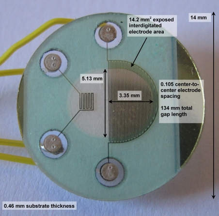
The following photo shows the physical size of the sensor and the portion of its interdigitated electrodes that is not covered by an insulating mask:
The electrodes appear narrower using diffuse light when there is not a direct reflection from them (as in the above photo), but wider using reflected light. Using reflected light, the electrodes look wider than they do using transmitted or diffuse light, with a width/separation ratio of as much as W/S = 2.7. However, careful measurement using directly reflected, diffuse and transmitted light under a microscope shows a W/S = 1.45 on average, and in the range 1.39 < W/S < 1.55.
The sampling area of the interdigitated electrodes is approximately 13.7-14.2 mm2. The manufacturer's drawing specifies it as 0.0192 in2 which is 12.26 mm2. Each electrode's area is approximately 3 mm2.
Interdigitated electrodes
The cell constant of the sensor is the proportionality constant between the measured conductance and the fluid's conductivity, as,
where,
K is the cell constant, in cm-1, and,
σ is the solution conductivity, in S/cm or µS-cm-1.
For a cell with parallel planar electrodes, the cell constant is the ratio of the separation of the electrodes divided by their area, as,
with dimensions of cm-1.
For interdigitated electrodes the cell constant is more difficult to determine; it depends nonlinearly on the widths and separation of the electrodes. While difficult to determine from theoretical considerations alone, I was able to simulate the electric field in the fluid surrounding the electrodes to find an effective cell constant. See Cell Constant of Interdigitated Electrodes for details.
For the interdigitated electrodes, I find the cell constant is given by1),
where,
S/W = the ratio of the separation between electrodes to the width of the metalized electrodes (about 0.69)
I find that this ⅓ power-law holds very well (within ±2% of simulated data) over the range 0.1 < S/W < 10. For our sensor geometry, this works out to:
Conductance/resistance ranges
Consequently, we should find the following range for measured conductances and resistances:
| Solution | Conductivity (µS/cm) | Conductance | Resistance |
|---|---|---|---|
| Pure deionized water | 0.055 | 0.42 µS | 2.38 MΩ |
| Power plant boiler water | 1 | 7.7 µS | 130 kΩ |
| Good city water | 50 (range: 5-500) | 384 µS | 2.60 kΩ |
| Blood | 6700 | 0.052 S | 19.2 Ω |
| "Normal" saline (0.90% w/v of NaCl) | |||
| Phosphate buffered saline | 13,500 – 17,000 | ||
| Ocean water | 53,000 | 0.408 S | 2.54 Ω |
| 31% HNO3 | 865,000 | 6.65 S | 0.15 Ω |
Conductivity standard solutions range from 1µS/cm to 200 mS/cm in value.
RTD temperature sensor
The RTD resistance at 20°C is about 340-380Ω. Of six sensors, I found resistances of 340, 367.2, 348.1, 362.8, 354.0, and 380.2 ohms. Unless the sensors can be made more reproducibly, they will need to be individually temperature calibrated.
Measuring the RTD geometry I find that its trace length and width are 15.75 mm and 0.054 mm. If the resistivity is that of pure gold (2.2x10⁻⁸ Ω-m at 20°C), then the thickness of the film must be,
t = ρ L / (W R) = 2.2x10⁻⁸ Ω-m * 15.75 mm /(0.054 mm * 360Ω ) = 178 Å
This thickness differs appreciably from the manufacturer's specification of 500 Å, suggesting that:
- the film is much thinner than the manufacturer's specification, or,
- the film is porous and not very dense, or,
- the deposition method was not clean enough, or,
- there is appreciable resistance in the contacts made to the film.
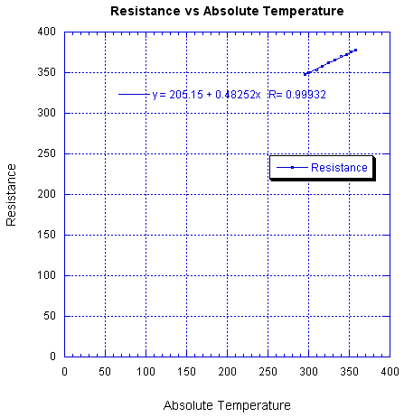
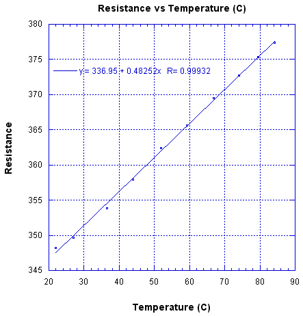
The temperature coefficient of resistivity also seems off. The manufacturer's data shows a linear change with temperature, which is good, but a large resistance intercept at zero temperature, which is bad. The data shows,
R = 205 + 0.4825 T
where R is resistance in ohms and T is in °K. The temperature coefficient of resistance is 1.4 x 10⁻³, instead of the 3.4 x 10⁻³ expected for gold. If the RTD were pure gold I would expect the following graph to intersect the origin,
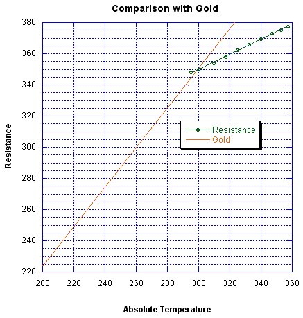
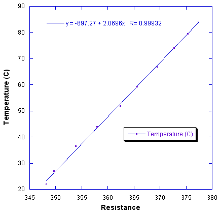
The temperature may be calculated from the resistance, for one particular sensor, using a linear equation as shown in the following graph:
See http://en.wikipedia.org/wiki/Electrical_conductivity_meter for temperature compensation factors.
See also → Conductivity Sensor Specifications

