Using the Conductivity Sensing Wildcard
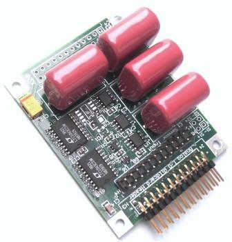
The Conductivity Sensing Wildcard is a precision instrument for measuring the electrical conductivity of ionic solutions. It converts the solution conductivity to an analog voltage that is precisely measured using the Analog I/O Wildcard's 16-bit A/D. The board may also be used in stand-alone operation, in which the output is measured with a handheld digital voltmeter or with a controller's built-in ADC.
Conductivity transmitter specifications
- 2 channels of conductance measurement
- Outputs of 0-1 volt, proportioned to a 1.000 V reference, or 0-4.9 V full scale.
- Directly connects to the 16-bit resolution inputs of the Analog I/O Wildcard
- Provides its own reference voltage which may be used as the reference for the Analog I/O Wildcard
- Operate stand-alone, with a voltage output, or connect it to any of Mosaic's microcontroller products.
- Very wide dynamic range of 100 – 106 microsiemens conductance, or 1Ω to 1MΩ resistance.
Theory of operation
Conductance and conductivity
The Conductivity Sensing Wildcard measures the ability of a solution to conduct electricity. In an aqueous solution, a current flows by transport of ions – the more the ions, the greater the conductivity.
The conductivity sensor actually measures conductance, or the inverse of electrical resistance. While resistance is measured in ohms, the unit for conductance is the inverse of the ohm, previously called a mho, and now defined as a siemen. As one siemen is a very large unit of conductance, aqueous samples are usually measured in microsiemens, μS, or millisiemens, mS.
The conductance measured depends both on the conductivity of the solution and the geometry of the electrodes. We are usually interested in knowing the conductivity, so we need to compensate the measurement for the electrode geometry. The geometry dependent parameter that relates the conductance to the conductivity is known as the sensor's cell constant. Given the cell constant, we can find the solution's conductivity, σ, as,
where,
K is the cell constant, in cm-1, and,
σ is the solution conductivity, in S/cm or µS-cm-1.
Electrodes and measurement technique
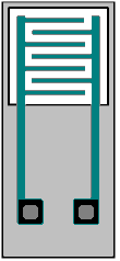
Conductance sensors comprise two electrodes of fixed geometry and spacing that are submerged in the liquid to be measured. Sometimes they are fabricated as a set of interdigitated electrodes on an insulating substrate, as shown in the figure. When placed in a conductive liquid, current flows between the electrodes in proportion to ion concentrations in the liquid. The electrodes use metals that are not easily corroded, such as gold, platinum or carbon.
The conductance of aqueous liquids is a constant for brief measurements at low voltage. For longer DC measurements or greater voltages the liquid doesn't behave linearly, but exhibits a nonlinear current-voltage relationship and memory effects. In particular, a DC current causes ions to build up on either electrode, resulting in electrode polarization.
To avoid these nonlinear effects, the Conductivity Sensing Wilcard takes these precautions:
- The measurement voltage is kept much smaller than the smallest voltage at which electrolysis can occur. Electrolysis starts at a little more than 1 volt; the Wildcard performs its measurements using only ±0.500 volts.
- Even at low voltages, if current persists too long bulk ion transport and deposition causes the build up of a space charge region at the electrodes, causing measurement nonlinearity. The Wildcard avoids this by using small currents and frequent polarity reversals. The maximum measurement current is limited to less than 50 µA1), and the frequency of the applied voltage is in the range of 2-2.5 kHz. Together, these factors limit the total charge deposition during each half of the applied AC waveform to less than 20 nC. For electrode areas of the order of 0.01 -1 cm2, ion deposition and surface space charge effects are limited to of the order of a few ppm of the surface area.
- The electrodes are capacitively isolated from the circuitry using low leakage film capacitors and the AC drive voltage is symmetric around ground to prevent any small DC current, even capacitor leakage currents. Even a small DC current, integrated over sufficient time, could cause electrode polarization.
- The fluid is isolated from the measurement circuit by high voltage capacitors. They prevent polarizing currents if the fluid is not otherwise isolated from voltage sources, as it might be if it is contained by a vessel that is improperly grounded.
Resistive divider
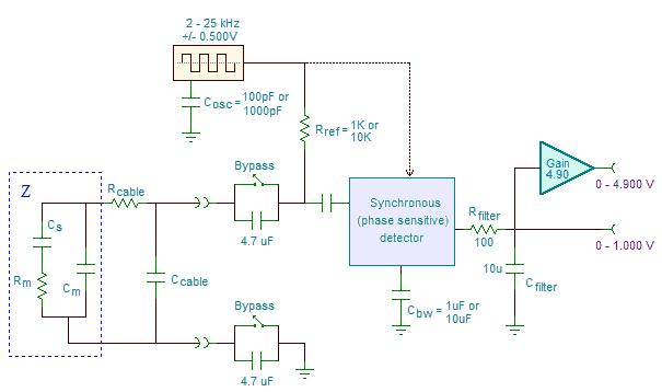
The following diagram2) illustrates the measurement circuitry:
At its heart, the circuit is a resistive divider driven by a small square wave at either 2.2 or 25 KHz. The divider's degree of attenuation is determined by the resistance of the conductance sensor. The attenuated AC voltage is rectified by a synchronous detector and presented to the output as a buffered 0 – 1.000 V or 0 – 4.900 V full scale signal. An internally generated 1.000 V reference is used to generate the ±0.500 V square wave signal. The reference is also provided as an output so that a connected A/D may use it as its reference. The output of the Wildcard may then be converted as a proportion of the 1.000V reference.
Measurement error
Using the 16-bit A/D converter of the Analog I/O Wildcard, quantization error is insignificant throughout most of the measurement range (200Ω to 5 MΩ), growing only to about 1% of measured resistance or conductance at either extreme.
Connecting to the Wildcard
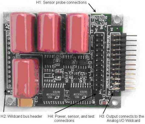
H1: Direct sensor connections
You may connect up to two conductivity probes to the card, at either H1 or H4. H4 is recommended as it also provide pins for connecting the probe's shield. Nevertheless, you can also connect the probes to header H1, at the following pins:
| H1 – Sensor Probe Header | |||
|---|---|---|---|
| Signal | Pins | Signal | |
| Sensor_1– | – 1 | 2 – | Sensor_1+ |
| Sensor_2– | – 3 | 4 – | Sensor_2+ |
Note that although the sensor signals are designated with (+) and (–) signs, the sensor probe is unpolarized and symmetric.
H2: Wildcard bus header
The Wildcard bus header is not generally used, and it should not be installed unless it is needed to pass signals to a board mounted above the Conductivity Sensing Wildcard. If it is installed, the +5V power may be used by the Wildcard if desired, and if power is not taken from the Analog I/O Wildcard. (For example, if the Wildcard is used in conjunction with the PDQ Board it may feed its output to the PDQ Board's 10-bit A/D's rather than the Analog I/O Wildcard's 16-bit A/D's.) In that case, zero ohm resistors R9 and R10 should be installed.
| H2 – Wildcard Bus Header | |||
|---|---|---|---|
| Signal | Pins | Signal | |
| DGND | – 1 | 2 – | +5V |
| – 3 | 4 – | ||
| – 5 | 6 – | ||
| – 7 | 8 – | ||
| – 9 | 10 – | ||
| – 11 | 12 – | ||
| – 13 | 14 – | ||
| – 15 | 16 – | ||
| – 17 | 18 – | ||
| – 19 | 20 – | ||
| – 21 | 22 – | ||
| – 23 | 24 – | ||
| Note:<block indent>While other signals are passed through the Wildcard Bus connector, only the +5V and digital ground (DGND) are used by the board.</block> | |||
H3: Analog output for connection to the Analog I/O Wildcard
The Wildcard provides outputs which can be directed to the Analog I/O Wildcard. The outputs provided are:
- A 1.000V reference to be sent to the external reference input of the Analog I/O Wildcard. The Analog I/O Wildcard should be configured to use this reference when reading the 1.0V full scale sensor outputs.
- Full scale outputs for each of the two sensing channels of 1.00V FS and 4.90VFS. The 1.00VFS output is used in conjunction with the 1.000V reference when using the Analog I/O Wildcard to measure the sensor outputs with high precision, and the 4.90VFS output may be used in stand-alone operation or for transmittal to other devices.
| H3 – Analog Output Header | |||
|---|---|---|---|
| Signal | Pins | Signal | |
| DGND | – 1 | 2 – | +5VAN |
| – 3 | 4 – | +VREF (1.000V) | |
| AGND | – 5 | 6 – | AGND |
| Out_2_4.9VFS | – 7 | 8 – | Out_1_4.9VFS |
| Out_2_1.0VFS | – 9 | 10 – | Out_1_1.0VFS |
| +VREF (1.000V) | – 11 | 12 – | |
| – 13 | 14 – | ||
| AGND | – 15 | 16 – | AGND |
| – 17 | 18 – | ||
| – 19 | 20 – | ||
| – 21 | 22 – | ||
| – 23 | 24 – | ||
| Note: 1. You normally connect this header to the Analog I/O Wildcard field header. 2. Pin 4 optionally connects to the onboard 1.000V reference through R26, a 0Ω resistor. 3. The 1.000V onboard reference always connects to Pin 11 (ADC3 input of the Analog I/O Wildcard). 4. The board's outputs connect to pins 7 to 10 where they may be read by ADC7 to ADC4. | |||
In normal operation you can connect this header to the field header of the Analog I/O Wildcard. In that case:
- The board is powered with +5V from the Analog I/O Wildcard via pin 2.
- The board provides a 1.000V reference to the Analog I/O Wildcard on pin 4.
- You read the outputs of the board's two conductivity channels on ADC channels 4 and 5 on pins 10 and 9 respectively.
H4: Sensor, test and power header
Header H4 is used for connecting the sensor probes, connecting alternate power if the Analog I/O Wildcard is not used, and for production testing. It has the following pinout:
| H4 – Conductivity Sensor and Test Header | |||
|---|---|---|---|
| Signal | Pins | Signal | |
| DGND | – 1 | 2 – | +VIN |
| VREF | – 3 | 4 – | +5VAN |
| V_SQ | – 5 | 6 – | +Vref (1.000V) |
| Shield_GND (AGND) | – 7 | 8 – | Shield_GND (AGND) |
| Sensor_1– | – 9 | 10 – | Sensor_2– |
| Sensor_1+ | – 11 | 12 – | Sensor_2+ |
| Sensor_1++ | – 13 | 14 – | Sensor_2++ |
| Out_1_1.0VFS | – 15 | 16 – | Out_2_1.0VFS |
| Out_1_4.9VFS | – 17 | 18 – | Out_2_4.9VFS |
| Test_1_10K (–) | – 19 | 20 – | Test_2_10K (–) |
| Test_1 (+) | – 21 | 22 – | Test_2 (+) |
| Test_1_10 (–) | – 23 | 24 – | Test_2_10 (–) |
| Note: Jumpers across pins 19-21, 21-23, 20-22, or 22-24 place 10Ω or 10KΩ resistors across sensor inputs for testing. | |||
In normal operation:
- Connect the first conductivity probe's electrodes to pins 9 and 11, and connect its shield to pin 7.
- Connect the second conductivity probe's electrodes to pins 10 and 12, and connect its shield to pin 8.
- No other connections need to be made to this header.
Calibration: At time of production some tests may be performed by placing jumpers mon H4 to connect on-board precision resistors to the channel inputs.
| Jumper location | Signal names | Input value |
|---|---|---|
| pins 19-21 | Test_1_10K-Test_1+ | A 10 KΩ 0.1% resistor is placed across sensor input 1. |
| pins 21-23 | Test_1_10 -Test_1+ | A 10 Ω 0.1% resistor is placed across sensor input 1. |
| pins 20-22 | Test_2_10K-Test_2+ | A 10 KΩ 0.1% resistor is placed across sensor input 2. |
| pins 22-24 | Test_2_10 -Test_2+ | A 10 Ω 0.1% resistor is placed across sensor input 2. |
Options
R9 and R10 are not installed when connecting the the Analog I/O Wildcard if the Wildcard bus header is installed. Install these if powering the Wildcard from a Mosaic controller, but not connecting to the Analog I/O Wildcard, or when connecting to an Analog I/O Wildcard but not connecting to the Wildcard bus.
Power can be supplied several ways:
- Normally, from the Analog I/O Wildcard by connecting from H3 to the Analog I/O Wildcard's field header.
- By applying +5V to the +5VAN pin of the sensor input header, H4 (pin 4). (And not connecting the Analog I/O Wildcard.)
- By applying +8 to +26V to the +VIN pin of the sensor input header, H4 (pin 2). (And not connecting the Analog I/O Wildcard.)
Software Drivers
The output of the Wildcard is usually read by the Analog I/O Wildcard. C-callable software drivers convert the measured voltage to a resistance or conductance. For more information about them, see:
- Detailed description of the equations implemented by the software drivers, and,
- The drivers are also implemented in an Excel spreadsheet for those using the board in stand-alone mode and manually computing the conductivity.
Modes of operation
Used with an Analog I/O Wildcard
You can mount the Conductivity Sensing Wildcard on any Mosaic controller and connect it to the Analog I/O Wildcard for precision measurement. In that case, you should make the following connections:
- On the Analog I/O Wildcard install jumper J6, and remove jumpers J3, J4, and J5 to configure the board to use the external 1.000V reference.
- On the Conductivity Sensing Wildcard a zero ohm short should be placed at R26.
- If the Wildcard bus header, H2, is installed on the Conductivity Sensing Wildcard, do NOT install resistors R9 and R10; otherwise, they may be installed.
- Wire a cable from the Wildcard's output header, H3, to the field header of the Analog I/O Wildcard. You should only include wires for the following signals:
- Pin 2 – +5V input to the Wildcard
- Pin 4 – VREF from the Wildcard to the Analog I/O Wildcard
- Pins 5 and/or 6 – Analog ground
- Pin 9 – Out_2, a 1VFS conductivity output signal going to the Analog I/O Wildcard's ADC_5 input.
- Pin 10 – Out_1, a 1VFS conductivity output signal going to the Analog I/O Wildcard's ADC_4 input.
- Wire the conductivity probe inputs to the Wildcard's Sensor/Test Header, H4, as:
- Probe 1 electrodes to pins 9 and 11.
- Probe 1 shield to pin 7.
- Probe 2 electrodes to pins 10 and 12.
- Probe 2 shield to pin 8.
Used with a Mosaic Controller's A/D
Mounted on a Mosaic controller and measuring the Wildcard's output with the 0-5V analog inputs of the controller.
On the Conductivity Sensing Wildcard, install resistors R9 and R10. These enable the Wildcard to draw its power from the Wildcard bus.
The output of the Conductivity Sensing Wildcard is measured by connecting its Out_4.9VFS outputs (pins 7 and 8 on H3 for OUT_4.9FS_2 and OUT_4.9FS_1) to the A/D inputs of the Mosaic Controller board.
Stand-alone operation
You can use the Wildcard without connecting it to a PDQ Board or other Mosaic controller if you wish. For detailed instructions on using the board stand-alone, see,
To manually perform the computations needed to convert the voltage output of the board to conductivity, download and use the Excel spreadsheet:
For stand-alone operation, on the Conductivity Sensing Wildcard DO NOT install resistor R9 and DO install resistor R10. There are two options for powering the board:
- If the chip at location U4 is installed, you can power the board from any voltage from +6.7 to +30 VDC, applied to +VIN (pin 2) and ground (pin 1) of Sensor Header H4. In that case, a zero ohm short must be installed at location R10.
- If U4 is not installed, you must supply a well regulated +5 V to the board. Apply the +5 V to pin 2 of header H3, and apply the power supply ground return to either of pins 5 or 6 of H3.


