Installing and Using Your EtherSmart Wildcard
EtherSmart Wildcard hardware
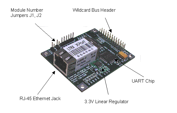
The following figure illustrates the hardware on the EtherSmart Wildcard. The large device is the XPort from Lantronix, providing an Ethernet co-processor and network server interface built into an RJ-45 connector housing. An Ethernet extension cable is available from Mosaic if you need to bring the female RJ-45 jack out to a panel connection on the front or back of your instrument.
A small linear regulator on the Wildcard converts the 5 volt power on the Wildcard bus to the 3.3V supply required by the XPort. The XPort draws about 250 mA of current. The regulator can be shut down under program control while the XPort is not in use to save 1.25 Watts for low-power instrumentation applications.
The XPort exchanges data via a serial UART-USART interface, while the Wildcard bus is a parallel interface. A UART (Universal Asynchronous Receiver/Transmitter) chip on the EtherSmart board implements the conversion between the parallel Wildcard bus and the XPort’s serial data lines. The UART contains two 64-byte FIFO (First In/First Out) buffers, one for incoming data, and one for outgoing data. The XPort and the UART "handshake" with one another using "Ready to Send" (RTS) and "Clear to Send" (CTS) hardware lines. This scheme ensures that no data is lost due to buffer overflow in the UART or the XPort: the sending device stops transmitting until the receiving device indicates that there is room in its buffer for more data.
The EtherSmart Wildcard.
| Physical Specifications | |
|---|---|
| Current: | 250 mA from 5V |
| Weight: | 25 gram |
| Size : | 2" x 2.5" x 0.55"1) (50.8mm x 63.5mm x 14mm) |
Connecting and addressing the Wildcard
You connect and address the EtherSmart Wildcard just as you would connect the WiFi Wildcard; see its connection instructions and addressing instructions.
See also → Installing and Using Your EtherSmart Wildcard

