Typical Motor Specifications
For widely available general purpose motors that can be used with the Motor Control Wildcard
This page provides the mechanical and electrical specifications for some of the motors and speed encoders that may be used with the Motor Control Wildcard. These motors are useful for many robotics and automation applications.
Allied Motion CL66 Motor
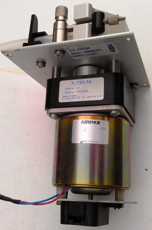
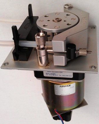
The Allied Motion CL66 motor is often used to actuate peristaltic pumps. It's a 12V 30 W motor with the following physical and electrical specifications:
| Part number | Series 9904-120-13.111) |
|---|---|
| Nominal power | 30 W |
| Nominal voltage | 12 V |
| Nominal unloaded current | 0.12 A max |
| Nominal torque | 80 mNm |
| Starting torque @ 12 V | 262 mNm |
| EMF @ 3000 rpm | 12.8 V |
| Unloaded speed | 2700 rpm (45 rps) |
| Nominal loaded speed | 1800 rpm |
| Nominal loaded power | 25 W |
| Nominal loaded current | 2.1 A |
| Starting current | 7.6 A |
| Internal resistance | 1.5 Ω |
| Mechanical response time | 25 msec2) |
| Rotor inductance | 1 mH |
| Rotor moment of inertia | 21.4×10⁻⁶ Kgm2 |
| Datasheet | Pump & obsolete motor datasheet Allied Motion website Allied Motion CL66 motor specs |
The starting current is likely not needed for starting the motor, rather, it is the stall current drawn if the supply does not limit the current. If a limited current is supplied, the motor will still develop a torque proportional to the supplied current, and still start.
The motor is connected through a 5:1 gearbox to a peristaltic pump head, which turns at a rate of 10-400 rpm to pump 50-250 ml/min.
The following photographs show the motor (marked AIRPAX), with optical encoder on the bottom shaft and a 5:1 gearbox on the top shaft, driving a peristaltic pump head.
US Digital optical encoder
The speed of the motor is monitored with a US Digital optical encoder (PN E5-32-157-NE-S-D-G-B). This encoder is a 32-quadrature cycle, 5 V logic output encoder iwth the following specifications specifications:
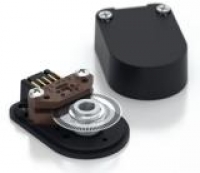
The encoder cable pinout is:
| Pin | Color | Description | 10-pin connector on the Rev 2 Motor Control Wildcard 3) |
|---|---|---|---|
| 1 | Brown | Ground | 5 (ground) |
| 2 | – | – | – |
| 3 | Blue | A channel | 1 (pulse input) |
| 4 | Orange | +5 VDC power | 10 (+5 V) |
| 5 | Yellow | B channel | 2 (other pulse input) |
The following table lists measured motor speed and encoder pulse rate (for a single encoder output) as a function of applied duty cycle at 12V and other supply voltages. The motor was unloaded except for the gearhead, peristaltic pump, and empty pump tubing. Note that this data provides the transfer function for the motor operated open-loop, without the Motor Controller Wildcard's PI control loop activated.
| Condition Voltage \ DC | Motor speed (rpm) | Encoder pulse rate (Hz) | Pump speed (rpm) | Pump flow4) (ml/min) |
|---|---|---|---|---|
| 14V 100% | 2756 | 1470 | 551 | 345 |
| 12V 100% | 2343 | 1250 | 469 | 294 |
| 10V 100% | 1933 | 1031 | 387 | 242 |
| 12V 10.3% | 0 | 0 | 0 | 0 |
| 12V 13.8% | 105 | 56 | 21 | 13 |
| 12V 20.7% | 300 | 160 | 60 | 38 |
| 12V 31.0% | 544 | 290 | 109 | 68 |
| 12V 41.4% | 782 | 417 | 156 | 98 |
| 12V 51.7% | 1043 | 556 | 209 | 130 |
| 12V 69.0% | 1399 | 746 | 280 | 175 |
| 12V 79.3% | 1674 | 893 | 335 | 209 |
| 12V 89.7% | 1974 | 1053 | 395 | 247 |
| 12V 100% | 2329 | 1242 | 466 | 291 |
| 12V 100% | 2343 | 1250 | 469 | 294 |
These measurements are plotted in the following graph, with the data in this spreadsheet.
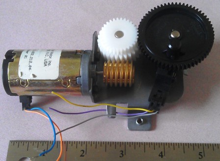
Buehler Motor PN 1.13.022.212.04
This useful little DC motor is usually provided in an assembly with a speed reduction gear and slots for an optical encoder. Unloaded at 12 VDC it draws 55 mA and the output of the speed reduction gear spins at 51 RPM. The assembly comprises a brass worm gear driving a white plastic two-tiered gear, driving a 50 mm black plastic gear with a 8.3 mm plastic nib to provide reciprocating action, with a 1/2" radius of rotation on nib. The motor is 31 mm in diameter, 2 wire with two wires leads. The gears are mounted on a steel bracket. The overall dimensions are 5.5" x 3" x 2" high and weight is 340 gm.
| Measured motor current | |||
|---|---|---|---|
| Condition | Applied voltage | Current | Speed |
| No load | 12 V | 55 mA | 51 RPM |
| Stall | 12 V | 800 mA | – |
| No load | 24 V | 55 mA | 104 RPM |
| Stall | 24 V | 1700 mA | – |
Motor marked 93044-2909-12V-07623
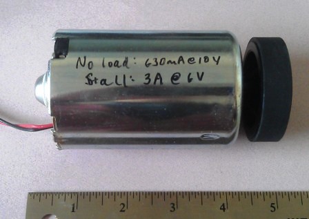
This massive motor operates on 12 VDC and produces tremendous torque. Size is 4" x 2.3" diameter. Shaft is 0.31" diameter "D" type x 0.85" long. Has color coded 8" long flexible leads. RPM at 12 VDC is 2700 and current is 0.64 amps (no load). This motor was designed for automotive use and has brute force! It is marked with part number 93044-2909-12V-07623, (although in many descriptions on component shopping sites it is mis-marked 93044-2909-12V-0763). Weighs 1.7 lbs. This motor is available from Electronic Goldmine and Amazon.
| Measured motor current | ||
|---|---|---|
| Condition | Applied voltage | Current |
| No load | 10 V | 630 mA |
| No load | 12 V | 640 mA |
| Stall | 6 V | 3 A |
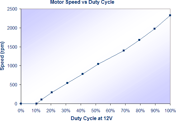
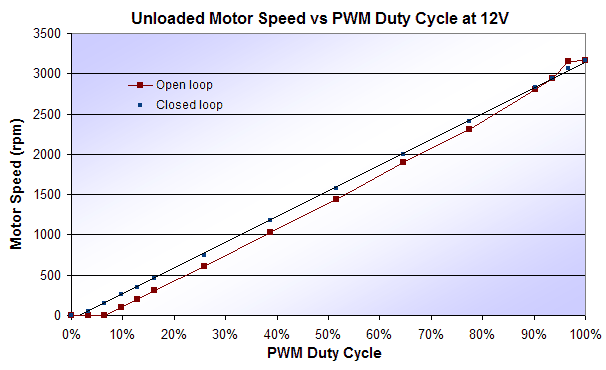
The following graph shows the motor speed as a function of PWM duty cycle when operated unloaded with a 12V supply with power pulse width modulated at a frequency of 50 KHz. Note that when running open-loop stiction at the low end prevents the motor from spinning until sufficient power is applied, and the speed isn't perfectly linear with applied power. The graph also shows the motor speed as a function of commanded speed (0–100%) when the speed is closed-loop controlled by the Motor Control Wildcard. In that case, there is still a little deliberate dead band around zero to assure positive turn off.
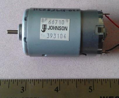
Johnson HC683LG-020
This very powerful 10.8 V motor is intended for use in electric screwdrivers and similar tools. It is rated for a no-load current of 2.38 A and a stall current 105 A. Its maximum output power 275 W. The Motor Control Wildcard can drive it at light loads.
| Measured motor current | ||
|---|---|---|
| Condition | Applied voltage | Current |
| No load | 12 V | 1.64 A |
| No load | 4.1 V | 1 A |
| Stall | 4.1 V | 2.2 A |
| Stall | 5.5 V | 3 A |
9.68:1 Gearmotor
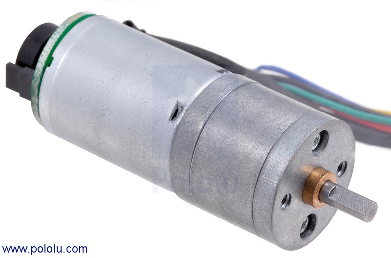
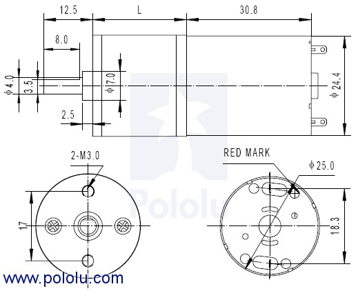
This small gearmotor is available from Pololu as PN 2271, 9.68:1 25Dx48L mm HP with 48 CPR Encoder. We purchased it from Jameco as Jameco Part no. 2205763.
| Specifications | |
|---|---|
| Size | 25D x 60L mm |
| Weight | 3.35 oz |
| Shaft diameter | 4 mm |
| Gear ratio | 9.68:1 or, (22x22x24)/(12x10x10) |
| Free-run speed | 1010 rpm at 6 V |
| Free-run current | 450 mA at 6 V |
| Stall current | 6000 mA at 6 V |
| Stall torque | 17 oz·in at 6 V |
| Lead length | 8 in |
It has an integrated 48 CPR magnetic quadrature encoder on the motor shaft, which provides 465 counts per revolution of the gearbox’s output shaft. The quadrature encoder provides two square wave pulses, 90° out of phase, each 12 pulses per revolution, giving 48 total transitions per revolution. If the rise time of only one output is used, there are 12 pulses per motor revolution, or 116.16 counts per output shaft revolution.
Encoder and wiring
A two-channel Hall effect encoder is used to sense the rotation of a magnetic disk on a rear protrusion of the motor shaft. The quadrature encoder provides a resolution of 48 counts per revolution of the motor shaft when counting both edges of both channels. To compute the counts per revolution of the gearbox output, multiply the gear ratio by 48. The motor/encoder has six color-coded, 11" (28 cm) leads terminated by a 1×6 female header with a 0.1″ pitch. The following table describes the wire functions:
| Color | Function |
|---|---|
| Red | motor power (connects to one motor terminal) |
| Black | motor power (connects to the other motor terminal) |
| Green | encoder GND |
| Blue | encoder Vcc (3.5 – 20 V) |
| Yellow | encoder A output |
| White | encoder B output |
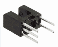
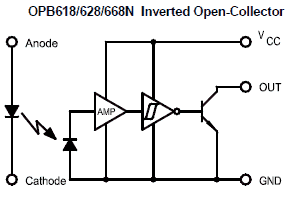
Slotted optical switch
| Pinout | |
|---|---|
| Pin | Use |
| 1 | Anode |
| 2 | Cathode |
| 3 | VCC |
| 4 | Output |
| 5 | Ground |
| OPB618 Specifications | |
|---|---|
| Electrical | Inv-Open Collector |
| Slot Width / Depth | 0.150" / 0.240” |
| Lead Length / Spacing | 0.100" (min) / 0.275" |
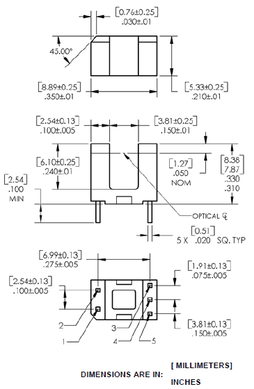
Taken from OPB618 datasheet.

