Motor Control Wildcard
Overview and specifications
Overview
The Motor Control Wildcard is a bipolar (H-bridge) output, controlled current driver for brushed DC motors. Use it to control the speed and direction of a DC motor. It's bipolar H-bridge output can supply controlled positive or negative currents up to a maximum of 3.3 A from field supply voltages up to 28 V. The board incorporates a tachometer and proportional-integral closed-loop speed controller for motors with optical encoders. You can use the board to control the power, speed or torque of DC motors, or supply currents to other loads including heaters and thermoelectric coolers.
When used with a Mosaic controller, motor direction and current (or speed) is set by software; used with other microcontrollers the board is commanded by a simple parallel hardware interface.
For a complete description of the board and all its functions, see the User's Guide. For quick start guides to using the Wildcard, please consult the following pages:
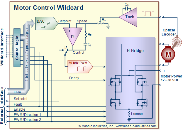
The functionality of the Wildcard is illustrated by the following block diagram of Fig. 1.

The diagram illustrates these salient features;
- The heart of the board is an H-bridge driver, which efficiently pulse width modulates (PWM) voltage from an externally applied power supply to the motor winding. The motor's speed is roughly proportional to the PWM duty cycle.
- When connected to a Mosaic Controller, the board is controlled through the Wildcard Bus, using commands of its software library. Those commands allow you to set the motor's state (braked, free-wheeling), direction, and speed/PWM setpoint. An internal DAC converts a 5-bit speed/PWM command into an analog setpoint.
- If the motor has an attached optical encoder for monitoring its speed, the encoder's output connects to an onboard tachometer. The tachometer converts the pulse frequency of the encoder to an analog speed signal, which appears on an output pin of the board, and can be used internally to control the motor speed.
- There are two options for the speed/PWM setpoint depending on the position of a hardware jumper (J3). In one position the setpoint is converted into a duty cycle for a 50 kHz PWM signal, which then controls the H-bridge motor driver. In the other position the setpoint is interpreted as a speed setting, compared to the actual motor speed, and a PI (proportional-integral) control loop operates on the error. Its output then controls the duty cycle of the PWM signal sent to the H-bridge motor driver.
- An optional input connector, labeled External Interface in the diagram, allows you to use the board with other microcontrollers, including the Raspberry Pi.
Specifications
| Specifications | |
|---|---|
| Motor voltage | 12 – 28 V 1) |
| Absolute maximum motor power | 80 W (3.3 A at 24 V) |
| Output current | ±0 – ±3.3 A FS (full scale), for less than one minute with current internally limited2) ±0 – ±2.5 A FS continuously in free air3) Other current limit levels available with a change of resistor value. |
| Current control | 5-bit PWM control of 32 current levels, from zero to full scale in either direction, are programmed using a simple command. For stand-alone operation speed may be controlled using a potentiometer. |
| Motor control | The motor may be set by externally driving digital lines or by software to any of 5 states:
        CW — Clockwise, or positive current with any of 32 current levels
       CCW — Counter-clockwise, or negative current with any of 32 current levels
     coast — Outputs are set to high impedance
brake-high — Motor braked with both leads tied to the field voltage
brake — Motor braked with both leads grounded |
| PWM frequency | 50-52 KHz |
| Heat sink | None required beyond the board itself. The maximum on-board power dissipation is 4.9 W (4.3 W typically) at a current of ±3 A. |
| H-Bridge IC | DRV8842PWP motor driver IC |
| Current consumption | Motor current is draw from the motor voltage supply, an additional board current of 10 mA is drawn from the Wildcard Bus +5 V. |
| Efficiency | 82% into a resistive load (18% of the total power consumed is dissipated as heat by the board and may be an important consideration for thermal management within enclosures) |
| Weight | 23 gram |
| Size | 2" x 2.5" x 0.75" (50.8mm x 63.5mm x 19mm) |
Modes of operation
Controlled by a PDQ Board or QCard Controller
The Motor Control Wildcard provides full motor control functionality when mated to a PDQ Board or QCard Controller. In that case a full-featured software driver gives you complete control of motor speed and direction with a very simple API. See Quick Start for how to connect your motor and control it.
Controlled by a Raspberry PI or other microcontroller
A special connector on the Motor Control Wildcard allows you to connect it directly to a Raspberry Pi or other microcontroller. You can then control a motor's speed by sending it a 5-bit code for PWM or speed setpoint, by giving it an analog voltage as setpoint, or by directly PWMming digital inputs. See Raspberry Pi Operation to get a quick start.
Stand-alone operation
(potentiometer controlled)
You can use the board in stand-alone mode, without needing to connect it to a computer. In stand-alone operation you can command motor PWM or speed by providing an analog voltage signal, or by simply connecting a potentiometer. To get started, see the Stand-Alone Operation guide.
See also →
- The above block diagram is available in this (available MS Word file).
