Limiting In-rush Current in MOSFET Power Switches
Control the voltage slew rate of a MOSFET high side switch to limit in-rush current into downstream capacitors.
Here are some electronic soft-start power switch circuits for controlling the slew rate of a MOSFET switch. Why is that important? Rapidly turning ON power to some devices can compromise their lifetime and reliability owing to large in-rush currents into their input capacitors. In particular, some devices place large tantalum capacitors on their inputs to filter ripple from the input voltage, or to provide switching currents to downstream switch mode power supplies. Suddenly providing voltage to those tantalum capacitors can result in in-rush currents of hundreds or thousands of amperes for a short time, greatly exceeding their in-rush or surge current capability, and sometimes even resulting in a small explosion! Tantalum capacitors are particularly prone to fireworks. A slew-rate-limited soft-start switch solves this problem.
The in-rush load current problem is solved by using a MOSFET power switch circuit that slew-rate limits its output. Instead of allowing the switch's output voltage to bounce up to the full supply voltage almost instantaneously, if its rate of increase is limited the maximum current into any downstream capacitors is also limited. In fact, the current is proportional to the rate of change (slew rate) of the switched power rail voltage, as,
where C is the downstream capacitance and V is the switched voltage.
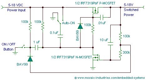
The MOSFET based soft start switch circuit of Figure 1 modifies a simpler latching switch circuit with the addition of a diode, resistor and capacitor to slew-rate limit the voltage rise at its output, the MOSFET's drain, resulting in surge-current-limited power switching:

The jumper can be permanently wired or set to control the default behavior of the circuit, whether it automatically turns ON (when the 0.1 μF capacitor is connected to the input power) or stays OFF (when the 0.1 μF capacitor is connected to ground), when power is first applied.
The circuit conveniently uses two MOSFETs packaged together, the IRF7319.
The addition of the 100 KΩ resistor and 0.01μF capacitor at the gate of the high-side MOSFET converts it into an integrating amplifier whose output rises linearly in response to a step change in its input, limiting the in-rush current to downstream capacitors. The values shown limit the slew rate of the voltage rise at the output to about 2V/millisecond. For a downstream capacitance of 1000μF, by Eqn. 1 the in-rush current is limited to 2A. Once the switch is fully ON, it is no longer current limited, and supplies the full load current.
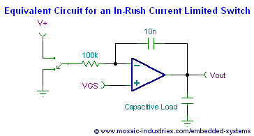
You can understand the circuit by considering the following equivalent circuit:

In the above soft start circuit, in the OFF state the switch is in the V+ position and the output is low (the MOSFET is OFF). Turning on the MOSFET is initiated by switching the switch to the ground position. Initially the MOSFET remains OFF as the feedback capacitor, Cf, discharges through the input resistor, Rgate, towards ground. The dead time continues until the voltage at the negative input of the amplifier (the MOSFET gate) reaches the gate's threshold voltage, shown as VGS in the schematic. At that point the MOSFET starts turning ON, entering its region of linear operation. It's operation holds the voltage at the negative input nearly constant1) as the output voltage rises linearly. The rate of output voltage rise is,
The voltage continues its linear rise until the MOSFET is fully turned on, and the output voltage saturates at the input voltage value. Then, the gate voltage continues its drop toward ground.
The output current into the capacitive load is limited, and equal to,
Knowing the load capacitance, you can choose Rgate and Cf to limit the in-rush current to any value desired.
The additional diode in the circuit assures that despite the modifications to the gate circuitry the circuit remains OFF when power is first applied, if the Auto-ON jumper is configured for that. The Auto-ON jumper connects the capacitor to ground to automatically turn ON the switch on power-up; if the jumper connects the capacitor to the input voltage the switch is held OFF on power-up. If you permanently wire the circuit for automatic turn on when power is applied, the gate diode is not needed.
To learn more about in-rush current protection, read this excellent Motorola application note:
You can apply the principles of this soft-start circuit to many other dual MOSFETs, including HEXFET, OptiMOS, PowerTrench, SIPMOS, STMOS, STripFET, and TrenchFET, from manufacturers Alpha & Omega Semiconductor Inc, Diodes Inc, Fairchild Semiconductor, Infineon Technologies, International Rectifier, NXP Semiconductors, ON Semiconductor, Renesas Electronics America, Rohm Semiconductor, STMicroelectronics, Toshiba, and Vishay Siliconix.
For example, any of these N-channel / P-Channel dual-MOSFETs should work:
Schematic files: TINA-TI Schematic file
