Controlled Turn-ON and Shutdown of Microcontroller Products
A simple MOSFET toggle switch circuit turns ON and initiates
orderly power shutdown for microcontroller based products
Electronic circuits are presented to implement a soft power switch for microcontroller based products. Many embedded computers do not include an ON/OFF switch. For example, Mosaic's SBCs or consumer computer boards, such as the Raspberry Pi or Arduino, simply turn ON when power is applied, and OFF when it is removed.
Often you will need to use a push button to turn an embedded system ON and OFF. Turning it ON is straightforward, power is simply applied and the microcontroller resets, initializes, and starts its application program. Powering it OFF is trickier – after pressing an OFF button some time should be allowed for the microcontroller to remain running so it can shut down its application program in an orderly way, and then turn itself OFF. If the microcontroller fails to turn itself OFF, a longer button press should be able to force it OFF.
Microcontroller soft power switch circuit schematic
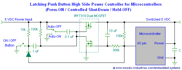
The circuit of Figure 1 implements this behavior, latching the switch ON with a button press, allowing a microcontroller to turn itself OFF at will or in response to another button press, and forcing the embedded system OFF with a long button press:

In this circuit, a momentary button press turns ON power to the microcontroller, and latches it ON. A second press can initiate shut down, or the microcontroller can turn itself OFF. A long press forces the system to turn OFF.
If you're looking for a simple Raspberry Pi project, or Arduino board project, this circuit will provide a valuable addition to those boards. If you're using a Raspberry Pi, see this Raspberry Pi ON/OFF circuit for a customized version of this circuit.
MOSFET switch turn ON and turn OFF
Here's what the MOSFET soft power switch does in more detail:
- When input power is first applied, the circuit comes up in its OFF state if the jumper is in the Auto-OFF position, or it turns ON automatically if the jumper is in the Auto-ON position. When OFF the circuit consumes no power, and when ON the only power dissipated is that in the P-MOSFET's small ON resistance.
- When your embedded system1) is OFF, a momentary button press turns it ON.
- When the embedded system is ON, a momentary button press does not affect the latch, but it can be detected by the processor pin if it is configured as an input capture. The processor can then implement an orderly shut down of the embedded system.
- The processor pin can also be used to turn OFF power. After the processor pin detects a button press, or at any other time determined by the application program, the processor pin can be reconfigured as an output pin. Subsequently, setting the output pin to an active low causes the latch to switch to its OFF state after several seconds.
- Ready or not, he embedded system can be forced to power down by pressing and holding the button for more than three seconds.
To use the circuit optimally, the microcontroller's application program should do the following:
- When the processor is first turned ON the processor's I/O pin should be configured as an input.
- Then configure the pin as an input capture so that it will call an interrupt service routine when it sees a falling edge.
- Your interrupt service routine should initiate a shut down of the application program and all the I/O it controls.
- Once the application is shut down, the application program should reconfigure the pin as an output and set it low.
- Setting the output pin low resets the MOSFET switches to their OFF state after several seconds, turning OFF the embedded system, including the processor.
Limiting in-rush or surge current
As shown, the above circuit does not limit in-rush current into the microcontroller's 5V bus. If you need current limiting, you modify the circuit with the addition of a diode, resistor and capacitor, as described in Limiting In-rush Current in MOSFET Power Switches.
Battery operation
The circuit of Figure 1 works well for input voltages from 5 to 18 volts. If you need a high-side power switch for operation from batteries, for example for voltages of 2V to 3.5V as produced by 2x AAA or 2x AA cells, then MOSFETs with lower gate threshold voltages are required. Suitable MOSFETs are shown in the schematics of Battery Operated Latching Power Switch
Turn ON turn OFF circuit for a handheld computer
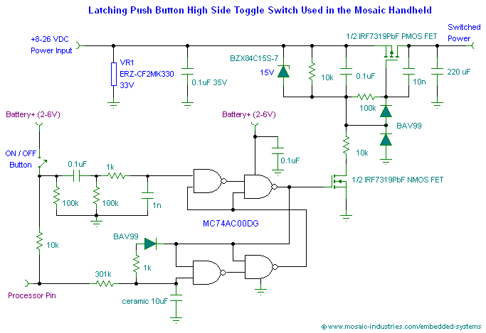
Finally, the following circuit shows the turn-ON circuitry for the Mosaic Handheld Controller:

In this in-rush-current-limited push-on-hold-off circuit, a button press can initiate an orderly shutdown of the microcontroller embedded system, or the microcontroller can initiate its own shutdown. A long button press forces shutdown. Current draw from the battery in the OFF state is negligible.
- Components used: IRF7319 Dual MOSFET
- Schematic files: TINA-TI Schematic file
