Connecting Thermocouples
Connecting a cold junction compensated thermocouple
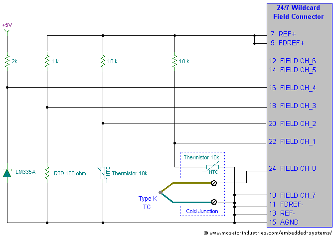
The following circuit diagram illustrates using a thermistor to cold junction compensate a thermocouple probe. While a thermistor is shown, you could also use an RTD, or the LM335A electronic sensor shown, so long as the sensor used is mounted on an isothermal block with the cold junction. The circuit diagram also shows other temperature sensors connected to a 24/7 Data Acquisition Wildcard.
The thermocouple probe is connected between CH_0 (the + input) and CH_7 (the – input), with CH_7 grounded to the analog ground. The thermocouple output varies from approximately -10 mV to +20 mV for a temperature variation from -200 to +500°C. When the A/D's BUFFER is OFF (that is, in unbuffered mode), the common mode range of the A/D extends to 30 mV below ground, so even when the thermocouple produces a slightly negative output it can be read by the A/D.
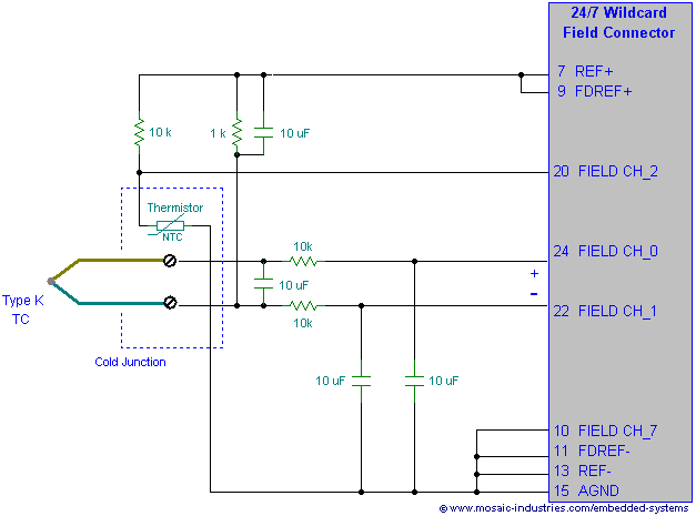
To assure that the thermocouple voltage lies within the A/D's common mode range, one side of the thermocouple is connected to the analog ground. If you use buffered mode (that is with the BUFFER turned ON) the common mode range of the A/D no longer extends to analog ground, so you must connect one side of the thermocouple to a voltage guaranteed to always be within the common mode range – connecting it to the +2.5V reference suffices, as shown in the following figure.
If the thermocouple is not connected to a fixed voltage within the converter's common mode range, but instead is allowed to float, then it may act as an antenna and pick up considerable noise.
When reading the thermocouple, bipolar mode is used so that both positive and negative voltages with respect to the negative input (CH_7) can be measured. It is read with a gain of 128, allowing an input range up to 19.5 mV.
The cold junction thermistor shown here is a standard 10kΩ at 25°C thermistor. It is placed in series with a precision 10kΩ ±0.1% resistor and driven from the 2.5V reference voltage. It is measured in pseudo-differential mode with a gain of unity, between channels CH_1 and CH_7.
The other sensors are measured as described in Measuring temperature sensors using the 24/7 Data Acquisition Wildcard.
See also → Connecting Thermocouples


