Cold Junction Compensation
Hot and cold junctions
One end of a thermocouple sensor comprises the junction which is placed on the object whose temperature is to be measured. At the other end of the wire pair, the thermocouple voltage is measured. However, additional thermocouple junctions are formed when connecting to the wire ends, so the total potential measured depends on the temperatures of those junctions as well as the junction at the measurement end of the thermocouple. Consequently, thermocouple voltages are relative values which must be measured with respect to a junction at a known temperature, called the cold or reference junction.
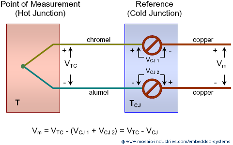
The following diagram shows a thermocouple used to measure the temperature at its hot junction, and the influence of the cold junction on the measurement.
The diagram shows a Type K thermocouple which uses nickel alloy wires, one made of chromel alloy and the other alumel. As shown in the diagram the thermocouple wires are usually terminated at a screw terminal block or connector. However terminated, the two connections should be made at the same temperature, so the cold junctions are often mounted on an isothermal block of high thermally conductive material with a large thermal mass.
Owing to the need to terminate the thermocouple wires at the cold junction the thermocouple potential of the hot junction can not be measured directly. Instead, the measurement voltage, vm, is the difference between the thermocouple voltage at the temperature to be measured (referred to 0°C, that is, the TC voltage minus its voltage at 0°C) and the thermocouple voltage at the cold junction (also referred to 0°C), as,
If the cold junction were truly at 0°C then vCJ would be zero volts and we would be able to measure the hot junction voltage directly. However, it is inconvenient to maintain the cold junction at 0°C, so in practice it's best to independently measure the cold junction temperature and use it to solve the above equation for vTC. Computing the hot junction potential, vTC, is called cold-junction compensation. It can be done one of two ways:
- A special electronic device mounted on the cold junction can add a small voltage in series with the thermocouple. Simple to use integrated circuits, like the LT1025A(Micropower Thermocouple Cold Junction Compensator), must be mounted on the cold junction block, with the thermocouple wires terminated right at the chip.
- The temperature of the cold junction can be independently measured using another temperature sensor (a thermistor, RTD, or integrated circuit temperature sensor). Then the cold junction's thermocouple potential is computed from its temperature using a numerical model of the thermocouple. The voltage addition is then done in software.
Either way, the computation performed is,
After the computation is done, the computed thermocouple voltage is that which would have been measured had the cold junction been at 0°C. That voltage can then be directly compared to the NIST TC data which is referred to 0°C.
Connecting to the thermocouple
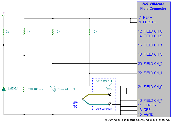
The following diagram illustrates using a thermistor to cold junction compensate a thermocouple. While a thermistor is shown, you could also use an RTD, or the LM335A electronic sensor shown, so long as the sensor used is mounted on an isothermal block with the cold junction. The diagram also shows other temperature sensors connected to the 24/7 Data Acquisition Wildcard.
The thermocouple is connected between CH_0 (the + input) and CH_7 (the – input), with CH_7 grounded to the analog ground. The thermocouple output varies from approximately -10 mV to +20 mV for a temperature variation from -200 to +500°C. When the A/D's BUFFER is OFF (that is, in unbuffered mode), the common mode range of the A/D extends to 30 mV below ground, so even when the thermocouple produces a slightly negative output it can be read by the A/D.
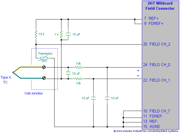
To assure that the thermocouple voltage lies within the A/D's common mode range, one side of the thermocouple is connected to the analog ground. If you use buffered mode (that is with the BUFFER turned ON) the common mode range of the A/D no longer extends to analog ground, so you must connect one side of the thermocouple to a voltage guaranteed to always be within the common mode range – connecting it to the +2.5V reference suffices, as shown in the following figure.
If the thermocouple is not connected to a fixed voltage within the converter's common mode range, but instead is allowed to float, then it may act as an antenna and pick up considerable noise.
When reading the thermocouple, bipolar mode is used so that both positive and negative voltages with respect to the negative input (CH_7) can be measured. It is read with a gain of 128, allowing an input range up to 19.5 mV.
The cold junction thermistor shown here is a standard 10kΩ at 25°C thermistor. It is placed in series with a precision 10kΩ ±0.1% resistor and driven from the 2.5V reference voltage. It is measured in pseudo-differential mode with a gain of unity, between channels CH_1 and CH_7.
The other sensors are measured as described in Measuring temperature sensors using the 24/7 Data Acquisition Wildcard.
Cold junction compensation using a thermistor
The above diagram shows a thermistor mounted on the cold junction to measure its temperature. That temperature measurement may be used to compensate the thermocouple reading as follows:
The thermocouple voltage is measured by the A/D using bipolar, pseudo-differential mode on channel pair CH_0/CH_7. The raw conversion result can be thought of as a 32-bit number, or as a 24-bit result that is left-justified within a 32-bit field. The midpoint of the 24-bit conversion result, that is 223, corresponds to a differential voltage of zero, positive voltages are represented by counts between 223 and 224-1, and negative voltages by counts between 223 and 0. This 24-bit result is left-justified within a 32-bit field.
The 32-bit A/D result is converted to a voltage by first dividing by 28 (or arithmetically shifting right by 8 places), subtracting 223 (which corresponds to the zero offset), dividing by the A/D gain (G = 128 = 27), and multiplying by the A/D's volts per count (5V/224). The result is now in volts. The full, but unoptimized computation is,
where CTC is the 32-bit count from the thermocouple, G is the A/D gain, and vm is the measured thermocouple voltage.
The thermistor voltage is measured similarly, in this case using unity gain and unipolar mode so that input voltages from 0 to 5V correspond to a 32-bit result (the A/D's 24-bit result left justified in a 32-bit long integer) from 0 to 232-1, with half scale, 231, corresponding to a thermistor resistance equal to the reference resistance. The A/D result is converted into the cold junction temperature, TCJ, using a rational polynomial function approximation, as described in Using Thermistors. The conversion is done in two steps. First the thermistor A/D counts are converted to a parameter, x, as,
where CTH is the A/D conversion result for the thermistor measurement and n=32. Then the cold junction temperature is computed as,
The cold junction temperature is converted into a cold junction thermocouple voltage using a polynomial or rational polynomial function approximation as described in Converting cold junction temperature to thermocouple potential, using an equation of the form,
Finally, the compensated thermocouple voltage is transformed into the measured temperature using a rational polynomial function approximation as described in Converting thermocouple voltage to temperature, using an equation of the form,
Several of the steps outlined above may be combined for greater computational efficiency. For example, instead of converting the thermistor A/C counts to a resistance, then to a temperature, then to an equivalent thermocouple cold junction potential, the operations of steps 2 and 3 above can be combined to convert more directly from A/D counts to the cold junction temperature using a single rational polynomial expression, as,
For type K thermocouple voltage in millivolts, and using a US Sensor Curve J 10kΩ thermistor, the coefficients of the above model are,
| Coefficients for converting Curve J thermistor counts to cold junction Type K thermocouple voltage (millivolts) | |
|---|---|
| Coefficient | Value |
| co | 1.0000 |
| c1 | -4.0257 |
| c2 | -7.3422 |
| c3 | 11.819 |
| c4 | 18.136 |
| c5 | 2.1406 |
| c6 | -3.5823 |
| c7 | -7.5824 |
The above model produces the cold junction potential with an average absolute error of 0.003°C over a range of 0 to +75°C. This cold junction voltage is then used in steps 4 and 5 above to compute the measured temperature. An Excel file of K type thermocouple data is available showing the data used in this fit.
See also → Cold Junction Compensation


