Appendix C: Schematics
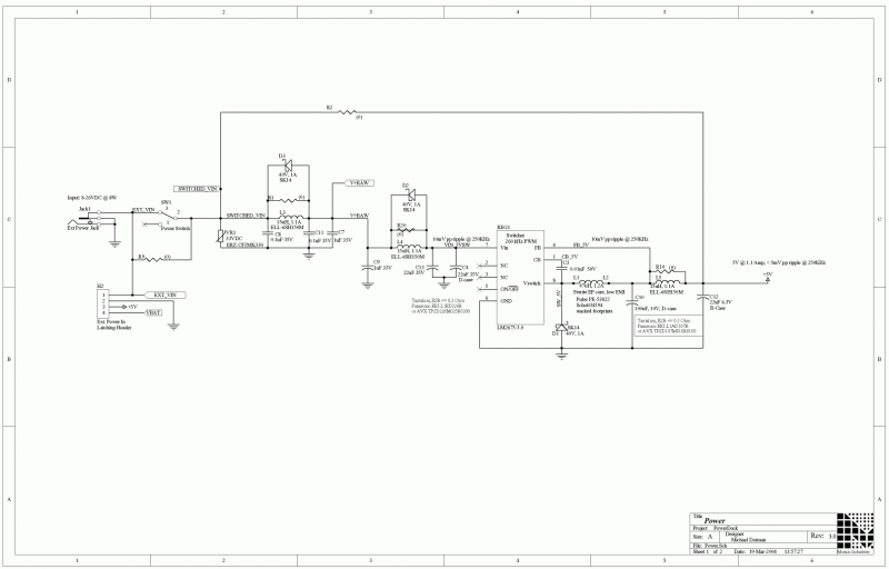
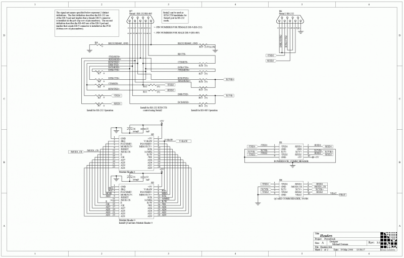
Electrical schematics for the QCard Controller embedded computer and Docking Panel power supply
The QCard Controller Starter Kit comprises two PC boards, designated the QCard Board and the PowerDock Board.
- The QCard Controller Single Board Computer (SBC) contains the Freescale 68HC11 microcontroller, RAM and Flash memory, digital input-output (I/O), and A/D.
- The PowerDock Board contains power conditioning, an additional Wildcard IO expansion port, power switch, power jack, and DB-9 serial connectors.
- This Appendix provides complete circuit schematics for each board.
For more info
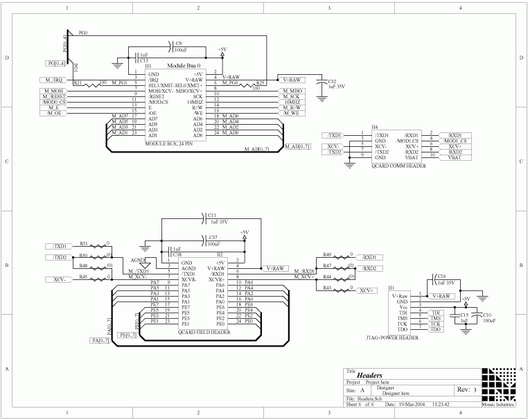
For more complete information about the QCard headers listed on this page, please see Getting to Know Your QCard Controller. Other pages in this QCard Controller Users Guide provide information on how to code C-language instrument control applications using the board.
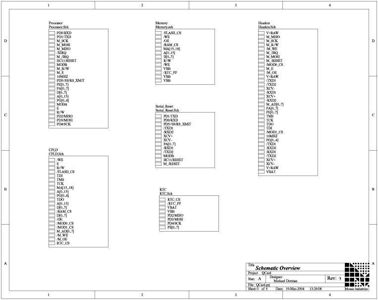
QCard schematics
QCard signal directory
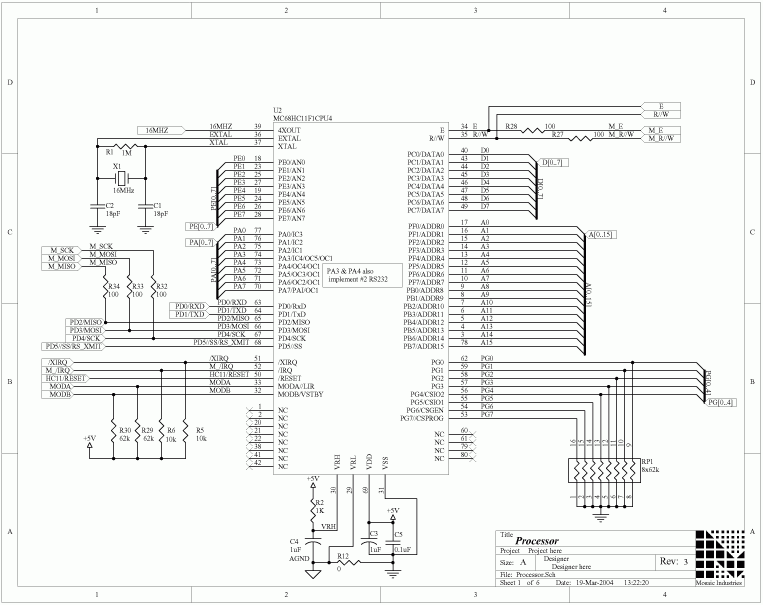
QCard processor
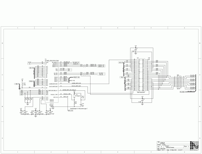
QCard CPLD
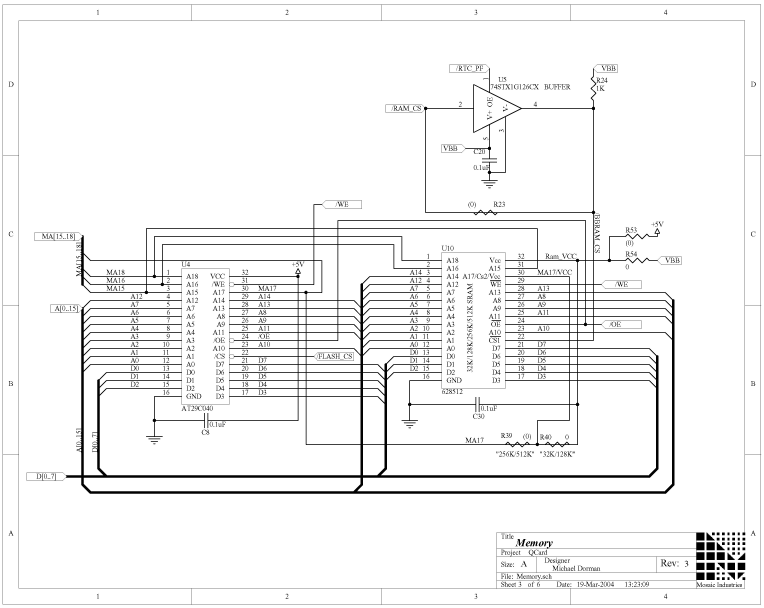
QCard memory
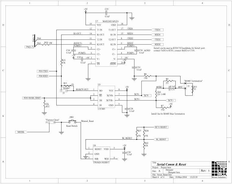
QCard serial and reset circuitry
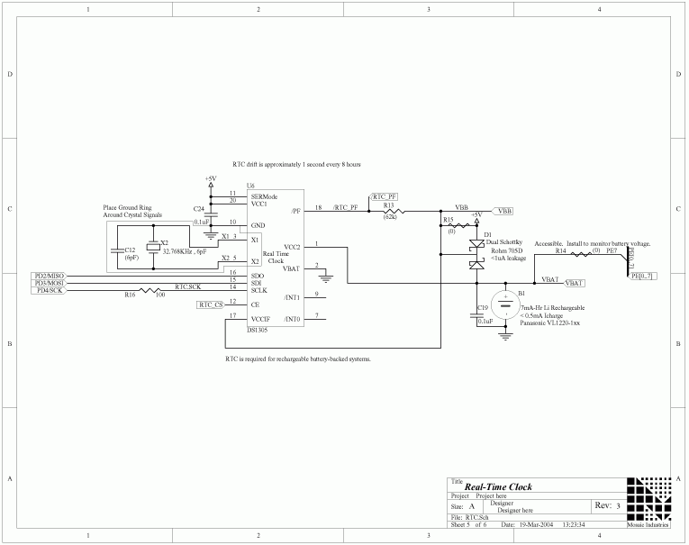
QCard real time clock
QCard headers
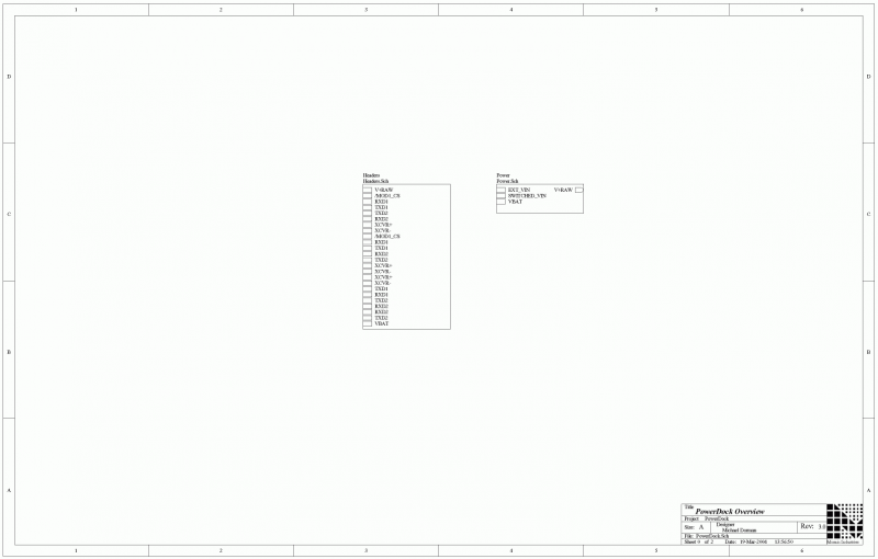
PowerDock schematic
PowerDock signal directory
PowerDock power circuitry
PowerDock headers
PDF schematics
This page is about: Electronic Hardware Schematics for QCard Controller Starter Kit, 68HC11 Processor, RAM and Flash Memory, Digital IO, and ATD Converter, Power Conditioning, Power Switch, Power Jack, and DB-9 Serial Connectors – Schematics for the QCard Controller Starter Kit's two boards: the QCard Controller with 68HC11 processor, RAM and Flash memory, digital IO, and ATD converter; and Docking Panel with high efficiency switching regulator, power switch & jack, and DB-9 serial connectors.

