I2C Bus Electrical Specifications
The cable length limit for an I²C (IIC or I2C) serial bus is inversely proportional to the bus speed or clock rate
Every communication system has its own scope, and the I2C specification targets multi-drop, short range wired communication. It is ideally suited to communication between ICs on a printed circuit board, or communication between a processor board and nearby sensors where there is little cable capacitance. The lower the bus speed, the more cable capacitance that can be tolerated, and the longer the cable limit. Higher bus speeds require shorter cables.
I2C maximum cable length
I2C transmission distance, data rate, cable capacitance, and cable length limit
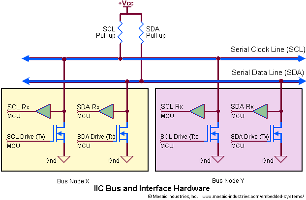
Devices on an I2C bus use open drain (or open collector) pins. Bus signals are actively pulled down by the communicating devices, but they are only passively pulled up by the pull-up resistors on each line. Consequently, the rate of a voltage transition from a logic low to high depends on the resistance value and the capacitance of the signal line. Figure 1 shows multiple devices attached to a single I2C bus.

For a given data rate, the maximum number of devices on the bus is limited by the capacitance on the SDA and SCL pins, and is also a function of the pull-up resistance values on the SDA and SCL lines. 4.7 Kohm pull-ups are installed on the SDA and SCL lines on the PDQ Board. Using the default pull-up values, the PDQ Board’s I2C port is capable of data transfer rates up to 100 kilobits per second with maximum bus loading of 170 picofarads (pF). Adding parallel 3.3K resistors to the SDA and SCL lines brings the equivalent pull-up resistance down to 2K, and allows 100 KHz signaling with bus capacitance as high as 400 pF. The HCS12 MCU can generate data rates up to 1 megabit per second, but accurate data exchange at these high rates requires very low bus loading (say, under 40 pF with 2K pull-ups). Lowering capacitive loading to these levels is difficult, and requires short cable lengths and very few peripheral devices on the I2C bus.
Alternate uses for the I2C I/O pins
PORTJ pins 6 and 7 may be used as general I/O pins
If the I2C bus is not needed, the associated HCS12 pins (PORTJ pins 6 and 7) can be configured as general purpose digital I/O , but note that the PJ6 (SDA) and PJ7 (SCL) signals are conditioned with 4.7K pull-up and 100 ohm series resistors.
- See: Using PORTJ

